




Container Closure Integrity Testing (CCIT) has undergone rapid technological advancement and gained increasing emphasis in pharmaceutical quality control in recent years. Traditional CCIT methods, including microbial challenge testing and dye penetration testing, are destructive analytical approaches characterized by lengthy test cycles, cumbersome operational procedures, and low detection accuracy. As probabilistic inspection methods, they are gradually phased out in industrial applications. The United States Pharmacopeia <1207> defines three mainstream deterministic CCIT methodologies, namely vacuum decay testing, high-voltage leakage detection (HVLD), and laser headspace gas analysis. Tofflon provides comprehensive non-destructive leak detection solutions covering the above three technologies, enabling customized selection of testing strategies based on specific packaging materials and product formulations. This paper systematically elaborates on the working principle, applicable scope, technical advantages and industrial implementation of HVLD technology, with a focused analysis on its practical application in the integrity verification of Blow/Fill/Seal (BFS) packaged products.
CCIT constitutes an indispensable core procedure for pharmaceutical packaging quality assurance. Annex 1 of EU GMP for Sterile Medicinal Products stipulates that package seal integrity shall be verified via fully validated methodologies. Specifically, 100% full inspection is mandatory for hermetically sealed products such as glass and plastic ampoules, while the integrity of other packaging forms shall be verified through standardized sampling protocols. USP <1207> establishes systematic specifications and mandatory requirements for pharmaceutical container closure integrity verification. Clause 77 of Annex 1 (Sterile Pharmaceuticals) in the Revised 2010 Chinese Good Manufacturing Practice (GMP) also clarifies that the seal integrity of sterile pharmaceutical packaging must be fully validated to prevent microbial and particulate contamination. Consistent with international standards, the Technical Guidelines for Container Closure System Integrity Research of Chemical Injectables issued by the Center for Drug Evaluation (CDE) of the National Medical Products Administration (NMPA) requires 100% integrity testing for all hermetically sealed products including glass and plastic ampoules, whereas other packaging types shall undergo routine sampling inspection per validated operating protocols.
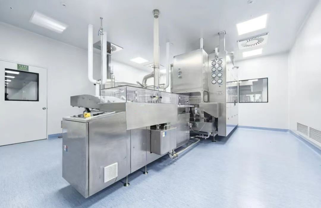
Blow/Fill/Seal (BFS) technology, originating from Germany, is an integrated aseptic packaging technology integrating in-blow molding, online filling and hermetic sealing. Initially applied to topical irrigant preparations, it was subsequently extended to small-volume injectable plastic ampoule products and has been widely adopted for large-volume injectable production since the 1980s. Currently, BFS technology is extensively utilized in the aseptic packaging of ophthalmic preparations, inhalation formulations, biological products and vaccines, enabling continuous, automated and high-volume manufacturing of unit-dose liquid pharmaceutical products. As a typical hermetically sealed liquid injection packaging form, BFS plastic ampoules are subject to compulsory 100% full CCIT. Targeted at the structural and packaging characteristics of BFS products, Tofflon has independently developed a dedicated in-line continuous HVLD system for BFS seal integrity inspection.
1. Detection Principle of HVLD Technology
HVLD technology performs non-destructive seal integrity detection by applying a specific high-voltage electric field to test samples and identifying micro-leakages based on differential electrical response characteristics between intact and defective packaging containers. Depending on production application scenarios, HVLD is classified into offline manual detection and online automatic detection, both of which require the internal filling liquid to possess qualified electrical conductivity.
Offline manual HVLD is primarily applied to in-process sampling verification. During testing, samples are placed on a grounded metal platform; operators wear professional insulating gloves to move the high-voltage electrode over the designated inspection area. Micro-pores, cracks or seal defects will break the packaging insulation, forming a conductive path between the internal conductive liquid and the high-voltage electrode, which generates visible blue electric arcs for defect identification.
Online automatic HVLD is a high-efficiency non-destructive testing technique based on Ohm’s law. The system adopts ultra-low operating current, which causes no structural or performance damage to pharmaceutical products and packaging materials while ensuring high-speed continuous detection.
For hermetically intact containers, the packaging wall maintains stable insulation, and only a weak induced microcurrent (I₁) is generated in the detection loop, serving as the baseline current of qualified products. The calculation formula is expressed as: I_1 = U / (Z_1+R+Z_2)
For defective containers with seal failure, insulation failure occurs at the leak point, leading to the disappearance of capacitance and capacitive reactance between the electrode and the container wall. The loop impedance decreases significantly, generating a markedly higher microcurrent (I₂). The calculation formula is expressed as: I_2 = U / (R+Z_2)
The system calculates the current difference Delta I = I_2-I_1 and compares it with the pre-validated threshold parameter to accurately judge whether the product has seal leakage defects. The high-voltage excitation mode effectively amplifies subtle current differences, enabling high-sensitivity identification of micro-scale leakages.
Notably, HVLD is not applicable to products with extremely low liquid conductivity such as pure Water for Injection (WFI). To expand the applicable scope of the technology, a pre-processing compensation strategy can be adopted in production. Specifically, a quantitative proportion of electrolyte (e.g., sodium chloride) can be added to the sterilization water bath. For defective products, the conductive sterilization medium penetrates into the container through micro-leakages, improving the overall conductivity of internal contents and meeting the basic detection prerequisites of HVLD.
The preconditions for valid HVLD detection are summarized as follows: the packaging material is electrically insulating; the internal pharmaceutical liquid has higher conductivity than the packaging material; the product is non-flammable and non-explosive; liquid medium can fully infiltrate the leak holes; and defect points are located within the effective detection range of the electrode. With a micrometer-level detection limit, HVLD technology is applicable to multiple pharmaceutical packaging forms, including rigid packaging (ampoules, vials, pre-filled syringes) and flexible packaging (large-volume infusion bags, BFS blow-fill-seal containers).
2. Structural Design of In-Line BFS Dedicated HVLD System
The first-generation in-line HVLD equipment emerged in the 1980s, which was limited by backward electronic control technology and mainly relied on button and knob manipulation plus relay control, with minimal application of Programmable Logic Controller (PLC) systems. Compared with offline single-station laboratory leak detectors, modern in-line HVLD systems possess prominent technical advantages, including fully automated unmanned feeding, continuous high-speed detection, automatic defective product rejection, and multi-station parallel testing. The equipment supports data interconnection with upstream and downstream production equipment, and is compatible with factory Supervisory Control and Data Acquisition (SCADA) and Manufacturing Execution System (MES), realizing intelligent and automated production management.
Given the significant differences in material properties and geometric structure between BFS products and traditional glass ampoules and vials, the overall mechanical structure and detection system of BFS HVLD equipment require customized targeted design. Traditional linear four-station HVLD equipment has inherent technical limitations: it cannot realize product flipping, resulting in undetected blind areas on the bottle body; meanwhile, single-direction horizontal detection leads to incomplete coverage of bilateral product areas.
To eliminate detection blind spots, an optimized structural design is adopted, realizing omnidirectional detection via product flipping and dual horizontal-vertical scanning. The complete system consists of a feeding system, primary vertical detection system, horizontal detection system, secondary vertical detection system, defective product rejection and collection system, discharging system and integrated control system.
The feeding system adopts a multi-stage segmented conveyor structure, composed of conveying belts, support plates, fixed brackets, variable-frequency drive motors and protective guardrails. Segmented conveyors are connected via smooth engineering plastic transition plates to avoid surface scratch damage to BFS products. The feeding system is divided into three functional modules: the inlet conveyor docks with the upstream BFS filling and sealing line, and can automatically tilt and discharge materials in case of downstream blockage or equipment failure to ensure uninterrupted upstream production; the acceleration conveyor increases the spacing between single products to provide stable spacing for subsequent sorting; the sorting conveyor precisely transports products to the detection station.
All conveyor modules are equipped with positioning guardrails to standardize product posture. A photoelectric sensing unit is installed at the front end of the sorting conveyor to monitor product in-place status. A quantitative discharging mechanism is configured at the sorting station to ensure uniform and continuous product feeding into the primary vertical detection system.
The primary vertical detection system, horizontal detection system and secondary vertical detection system constitute the core detection unit of the equipment. Through coordinated flipping and multi-angle scanning, the system realizes full-coverage detection of key sealing positions including the bottle head, bottleneck, bottle body, bottle bottom, bilateral sides and central sealing seams, completely solving the detection blind spot problem of traditional linear equipment.
3. Validation Scheme of BFS HVLD System
The performance validation of the BFS HVLD system adopts a comparative verification method based on qualified negative samples and defect-positive samples. Negative samples refer to intact BFS products with qualified sealing and no structural defects. Positive samples with standard micro-leakages are mainly prepared by laser drilling or microcapillary implantation. Laser drilling can stably fabricate standard micro-pores with a minimum aperture of 2 μm, applicable to both filled and empty BFS samples. Microcapillary implantation can simulate pores smaller than 1 μm, but has obvious limitations: glass microcapillaries are prone to breakage and blockage during implantation, and the surface protrusions formed after implantation are inconsistent with actual leakage defects, easily causing jamming during conveying. The actual leakage level of positive samples is calibrated by gas leakage rate, in accordance with domestic and international industrial guideline data correlating pore size and leakage rate.
System validation requires the preparation of gradient positive samples with typical pore sizes (2 μm, 5 μm, 10 μm) and multi-point defect distribution (bottle head, bottleneck, bottle body, bottle tail), with sufficient sample quantity for repeated verification. Before validation, the equipment shall be stably operated to eliminate bottle jamming, abnormal alarms and data acquisition failures, and confirm the normal operation of the automatic rejection system.
The key parameters for validation include detection voltage and current threshold. The detection voltage is determined iteratively from low to high, comprehensively considering product specification, packaging thickness, polymer material properties, filling volume and liquid conductivity. Meanwhile, voltage parameters shall be verified to ensure that repeated detection will not cause insulation breakdown or structural damage to qualified negative samples.
The current threshold is formulated based on statistical analysis of negative sample baseline current, with standardized steps as follows: (1) collect multiple groups of actual current data of qualified negative samples; (2) calculate the mean value (μ) of baseline current; (3) calculate the standard deviation (σ) of baseline current; (4) set the detection threshold higher than the statistical limit of μ+3σ to avoid false detection; (5) conduct no less than three rounds of mixed sample verification with positive and negative samples, to verify 100% accurate rejection of defective samples and 100% pass recognition of qualified samples, ensuring detection accuracy and stability.
After completing full-scale validation of multi-size and multi-position defect samples, the minimum detection limit and overall sensitivity of the equipment are confirmed. For daily production quality control, conductive and insulating simulated calibration samples are used for pre-production functional verification in each startup. The system is confirmed to be in normal working state when conductive simulated samples are accurately identified as defective products and insulating simulated samples are judged as qualified products, realizing rapid and effective daily performance confirmation.