Driven by rising chip TDP and large-scale cluster rollouts, liquid cooling has evolved from an optional upgrade into a foundational infrastructure for modern AI data centres. This paper examines prevailing cold plate architectures and the sharp upward shift in CDU hydraulic and thermal specifications across recent hardware generations, highlighting that component selection must be governed by real field operating conditions rather than datasheet ratings alone. It analyses systemic risks stemming from differential-pressure coupling failures, particulate fouling and tolerance stack-up when scaling from single-node assemblies to multi-megawatt facilities. Long-term reliability hinges on two core enablers: consistent, traceable manufacturing controls and structured lifecycle performance governance, complemented by end-to-end cleanliness protocols covering production, commissioning and live operation. The discussion outlines the three pillars of a holistic thermal solution — ecosystem integration, scenario adaptability and full-lifecycle management — and concludes that industry competition is shifting from standalone component performance to proven large-scale operational resilience. Sino Bioengineering differentiates itself through full-stack control over cold plate, CDU, manufacturing and on-site execution, with standardised, traceable processes to sustain stable thermal performance at scale.
01 Two Defining Trends Shaping AI Data Center Development
The rapid advancement of generative AI and high-performance computing workloads is driving two fundamental, interconnected trends across modern AI data center infrastructure: continuously rising thermal density and rapidly expanding deployment scale.
Thermal density at the server and node level is escalating at an accelerated pace. The Thermal Design Power (TDP) of leading AI accelerator chips continues to climb, while hardware architects pack an increasing quantity of high-density compute servers within a single rack unit. Compounding this challenge is the exceptionally compressed hardware iteration cycle characteristic of the AI industry. In many capital projects, technical planning and commercial alignment for next-generation accelerator platforms are already underway before the preceding hardware generation has completed full site deployment and stabilization. This creates continuous pressure on cooling infrastructure to support upward power trajectories without wholesale retrofitting of primary mechanical systems.
In parallel, liquid cooling has undergone a decisive paradigm shift: it is no longer treated as an optional, niche enhancement reserved for high-end test beds or limited pilot clusters. Today, liquid cooling constitutes an indispensable, mission-critical foundation for large-scale AI compute facilities. The industry is transitioning decisively from small, carefully instrumented proof-of-concept deployments toward mass rollouts spanning dozens, hundreds or even thousands of liquid-cooled racks. This scale expansion introduces a new dimension of systems complexity, including vastly expanded fluid distribution networks, thousands of mechanical connection points, heterogeneous rack configurations, and a broad spectrum of transient and steady-state operating conditions that are rarely fully captured in laboratory qualification environments.
02 Cold Plate Technology Evolution and Holistic System Requirements
The relentless upward trajectory of chip power envelopes has stimulated sustained innovation and diversification within cold plate thermal technology. The mainstream technical architectures deployed for direct-to-chip liquid cooling today include conventional single-phase cold plates, pin-fin enhanced cold plates, jet impingement cold plates, microchannel cold plates, and two-phase cold plate assemblies.
A foundational principle governs technology selection: no single cold plate topology delivers universally superior performance for all use cases. The optimal thermal solution must be derived from a holistic system-level design exercise that accounts for the mechanical envelope of the accelerator package, chip heat flux distribution, allowable junction temperature setpoints, fluid selection, and the upstream and downstream hydraulic boundary conditions of the cooling loop. Internal geometric modifications to cold plate core structures directly alter hydraulic behaviour, most notably pressure drop across the cold plate assembly. For this reason, cold plate hydraulic design cannot be isolated; it must be co-engineered in lockstep with circulating pump selection, Cooling Distribution Unit (CDU) hydraulic curves, manifold layout, and the primary facility-side heat rejection loop.
Performance requirements imposed on CDU hardware have risen dramatically over successive generations of AI accelerator hardware. In 2024, typical CDU unit capacities centred around 300 kW, with standard design flow requirements of approximately 1 litre per minute per kilowatt of thermal load and a target delivery pressure head of 30 psi. By 2025, market requirements shifted substantially, with standard CDU capacity scaling to 1.5 MW, required flow density rising to 1.5 litres per minute per kilowatt, and specified pressure head increasing to 60 psi. For 2026, the industry is seeing CDU specifications targeting capacities of 2.5 MW and above, while flow requirements are trending toward 2 litres per minute per kilowatt; flagship accelerator platforms such as Google TPU v5 impose pressure head requirements as high as 90 psi.
This progression underscores a non-negotiable engineering tenet: component qualification cannot rely solely on compliance with nominal datasheet ratings. Every fluid handling and thermal component must demonstrate stable, predictable, and failure-resistant performance under the full range of transient, off-nominal, and sustained operating conditions encountered within end-user production environments.
This lesson is clearly illustrated by a documented field event involving UQD quick-disconnect couplings. The observed failure mode was uncontrolled fluid leakage occurring during the mating sequence between open-loop sockets and plug connectors. Root-cause analysis identified that the differential pressure acting across the plug-socket interface at the moment of connection reached 150 psi, a loading scenario that had not been explicitly bounded, characterised or validated within the published UQD component specification.
Particulate contamination presents a second pervasive risk for quick-disconnect hardware. Facility-side filtration systems are commonly specified with a nominal retention rating of 300 micrometres. Hard particles exceeding this threshold can become trapped within the intricate internal flow passages of quick-disconnect couplings, leading to partial flow restriction, accelerated localised erosion, seal damage, or complete blockage over time. This reinforces that component selection matrices must be anchored to site-specific contamination controls, fluid chemistry and pressure cycling profiles, rather than drawing decisions exclusively from product specification sheets.
Of equal importance is the management of tolerance stack-up, a phenomenon that begins as minor component-level variation but can propagate into severe systemic risk at scale. At the individual component level, inherent manufacturing tolerances introduce small dimensional and performance deviations. When multiple components are assembled into a complete rack, cumulative deviations are amplified by variances in assembly sequence, fixture alignment, torque control and workmanship. Once extended across an entire facility comprising hundreds of racks, further divergence is introduced by inconsistent commissioning practices, variable setpoint configurations, staggered maintenance schedules and site-specific operational drift. The conclusion is unambiguous: dimensional and hydraulic tolerances that remain manageable and benign at the single-unit or single-rack level can compound into destabilising systemic hazards when deployed across multi-megawatt liquid cooling campuses.
03 Two Cornerstones for Sustained Long-Term System Reliability
Robust long-term reliability of large-scale liquid cooling deployments rests upon two complementary pillars: tightly controlled manufacturing consistency enforced prior to site deployment, and structured lifecycle performance governance maintained throughout the operational service life.
Manufacturing consistency establishes the baseline for predictable performance across every unit shipped. This pillar is built first upon harmonised, shared engineering standards across all production locations, ensuring material formulation, fabrication processes, assembly methodologies, acceptance test protocols and pass/fail criteria remain identical regardless of production site. Second, execution must be repeatable by design, achieved through heavy deployment of automated assembly tooling, precision fixtures, scheduled equipment calibration, and continuous in-process monitoring to suppress variability introduced by manual handling. Third, all performance outcomes must be fully verifiable and traceable: every functional test result is permanently linked to the complete manufacturing genealogy of the assembly, enabling engineering teams to isolate and validate root causes rapidly if field anomalies emerge.
Lifecycle governance preserves the integrity of the thermal system after it leaves the factory. This framework commences by establishing a validated baseline performance signature at the point of factory acceptance testing. During on-site installation and commissioning, procedures are designed to preserve the as-built system state and validate hydraulic, thermal and leak-tight performance across the full integrated loop boundary. After handover to operations, continuous monitoring tracks key process parameters including volumetric flow rate, differential pressure, supply and return fluid temperatures, and junction temperature telemetry to identify gradual drift before it escalates into outage risk. Finally, structured feedback channels route field performance data, failure observations and operational learnings back into the product development pipeline, closing the loop for iterative design refinement for future hardware generations.
04 Cleanliness Management: Contamination Control Across the Full Value Chain
Fluid cleanliness is a foundational control domain for direct liquid cooling systems, and contamination management must be implemented as a continuous discipline spanning production, commissioning and operational phases, rather than treated as a one-time inspection checkpoint.
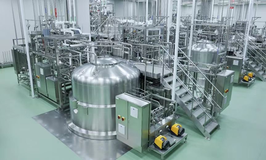
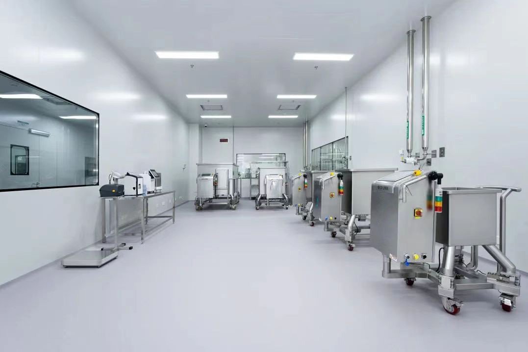
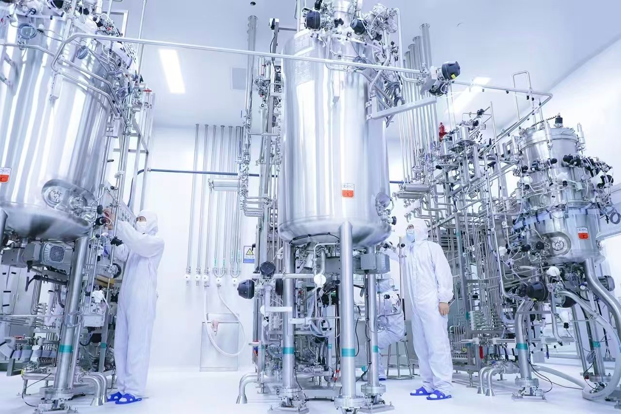
Within the production environment, controls include dedicated controlled assembly zones and cleanroom workflows where fluid-wetted components are integrated. Standardised, validated flushing and cleaning sequences remove residual machining swarf, particulate debris and surface contaminants from internal flow paths, and formal cleanliness verification is conducted prior to packaging and shipment.
During site commissioning, mandatory loop flushing regimes purge construction debris, welding slag, sealant fragments and other foreign material introduced during mechanical installation, manifold tie-in and rack plumbing activities, before computing loads are energised.
Once in operation, cleanliness is maintained through properly sized and positioned filtration trains, ongoing material compatibility surveillance to mitigate fluid degradation and corrosion by-product generation, flow velocity governance to minimise erosion and cavitation risk, and periodic coolant sampling paired with analytical testing programmes to track particle count, total dissolved solids, pH and additive concentration trends over time.
05 Three Pillars of the End-to-End Thermal Solution Portfolio
The comprehensive thermal solution architecture is structured around three interdependent pillars: ecosystem integration, targeted application adaptability, and full-lifecycle management.
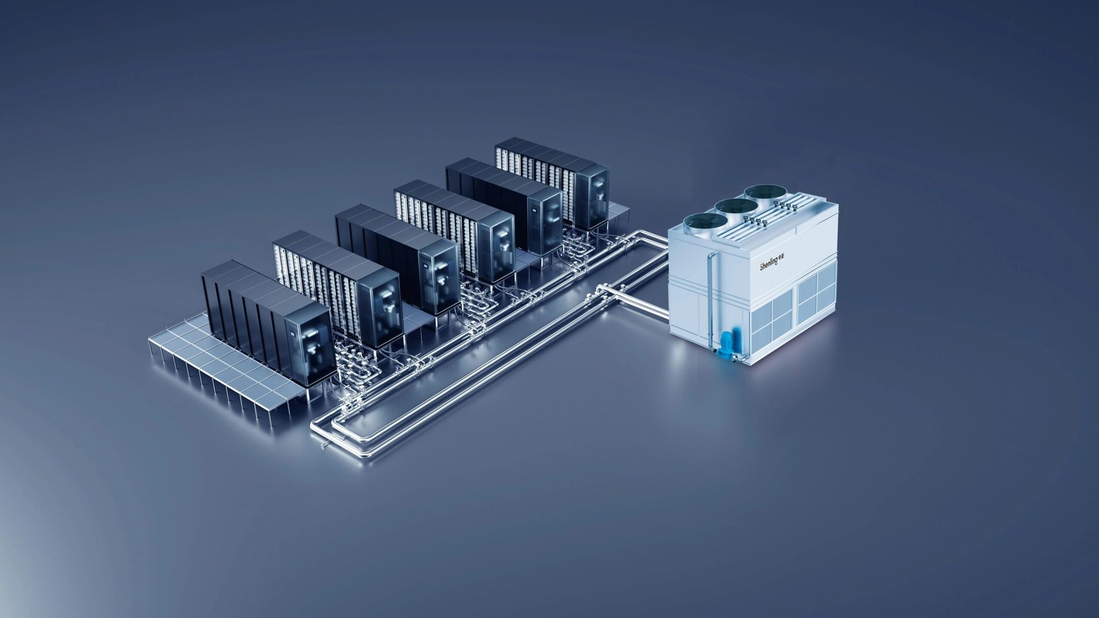
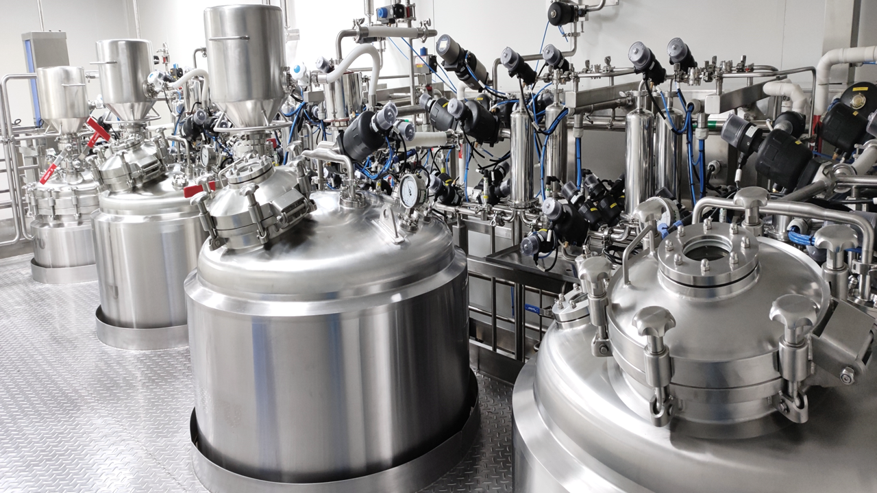
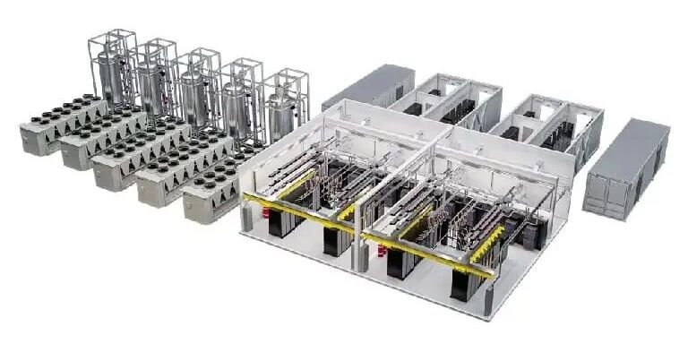
Ecosystem integration delivers a cohesive product stack that extends seamlessly from the node level, encompassing cold plates, quick-disconnect couplings, sealing interfaces and local sensor hardware, all the way to facility-scale equipment such as CDUs, fluid manifolds, distribution headers and formulated heat transfer fluids. Rather than supplying discrete, decoupled components, the entire fluid circuit is engineered, validated and supported as an integrated hydraulic and thermal system.
Application adaptability ensures the solution framework is equipped with supporting hardware, procedures and technical services tailored to every stage of the asset lifecycle. This covers laboratory characterisation and thermal qualification, production burn-in validation, data centre commissioning support, and steady-state operational oversight for production clusters.
Lifecycle management delivers end-to-end quality assurance and system health supervision spanning concept design, fabrication, factory acceptance, site installation, commissioning, routine operation and planned maintenance.
Competitive differentiation within the AI liquid cooling industry has transitioned definitively from headline benchmarking of isolated component performance toward the capability to deliver consistent, resilient and maintainable thermal performance at massive deployment scale. The distinctive advantage of Sino Bioengineering resides in its end-to-end governance capability across the entire liquid cooling stack. This spans cold plate and CDU design and manufacturing, controlled production execution, on-site deployment oversight, and ongoing operational support. By embedding standardised workflows, formal validation gates and full traceability controls at every stage of the system lifecycle, stable and predictable thermal performance can be reliably sustained within multi-megawatt direct liquid cooling infrastructure for high-density AI compute.