
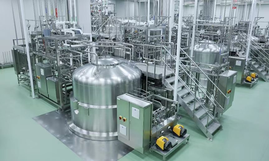
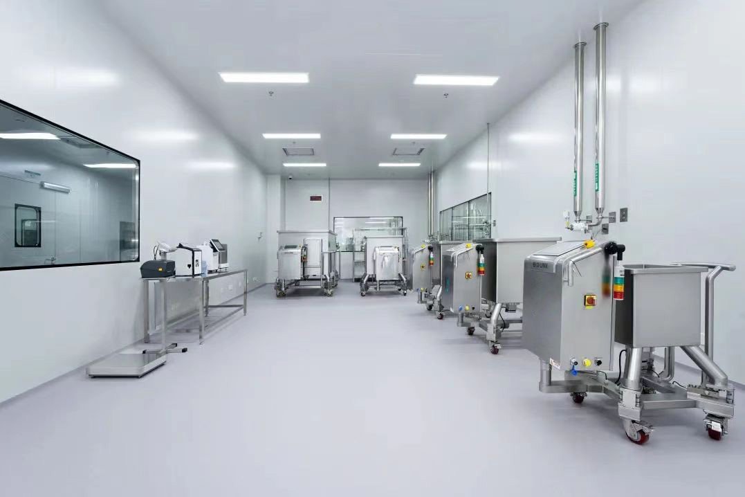

Cooling Distribution Units (CDUs) serve as the pivotal hydraulic and thermal interface between facility water loops and secondary technology cooling circuits for direct liquid-cooled AI and HPC data center infrastructure. This treatise delivers a systematic, component-centric dissection of CDU engineering, covering working principles, hydraulic isolation logic and core design rationales. It elaborates on the specification boundaries, performance trade-offs and reliability considerations for key subsystems, including centrifugal pumps, brazed plate heat exchangers, filtration packages, valve manifolds, process instrumentation and expansion tanks. Special emphasis is placed on pump architecture selection for in-rack and in-row CDU deployments, alongside coolant quality control, degassing strategy, and closed-loop control logic tailored for high-density compute loads. The content addresses critical engineering challenges such as cavitation suppression, leakage risk mitigation, fouling control, dew-point management and whole-lifecycle TCO optimization. It provides actionable technical guidance for thermal designers, system integrators and validation teams engaged in liquid cooling system specification, skid fabrication, commissioning and predictive maintenance.
1. Overview
1.1 Definition of CDU
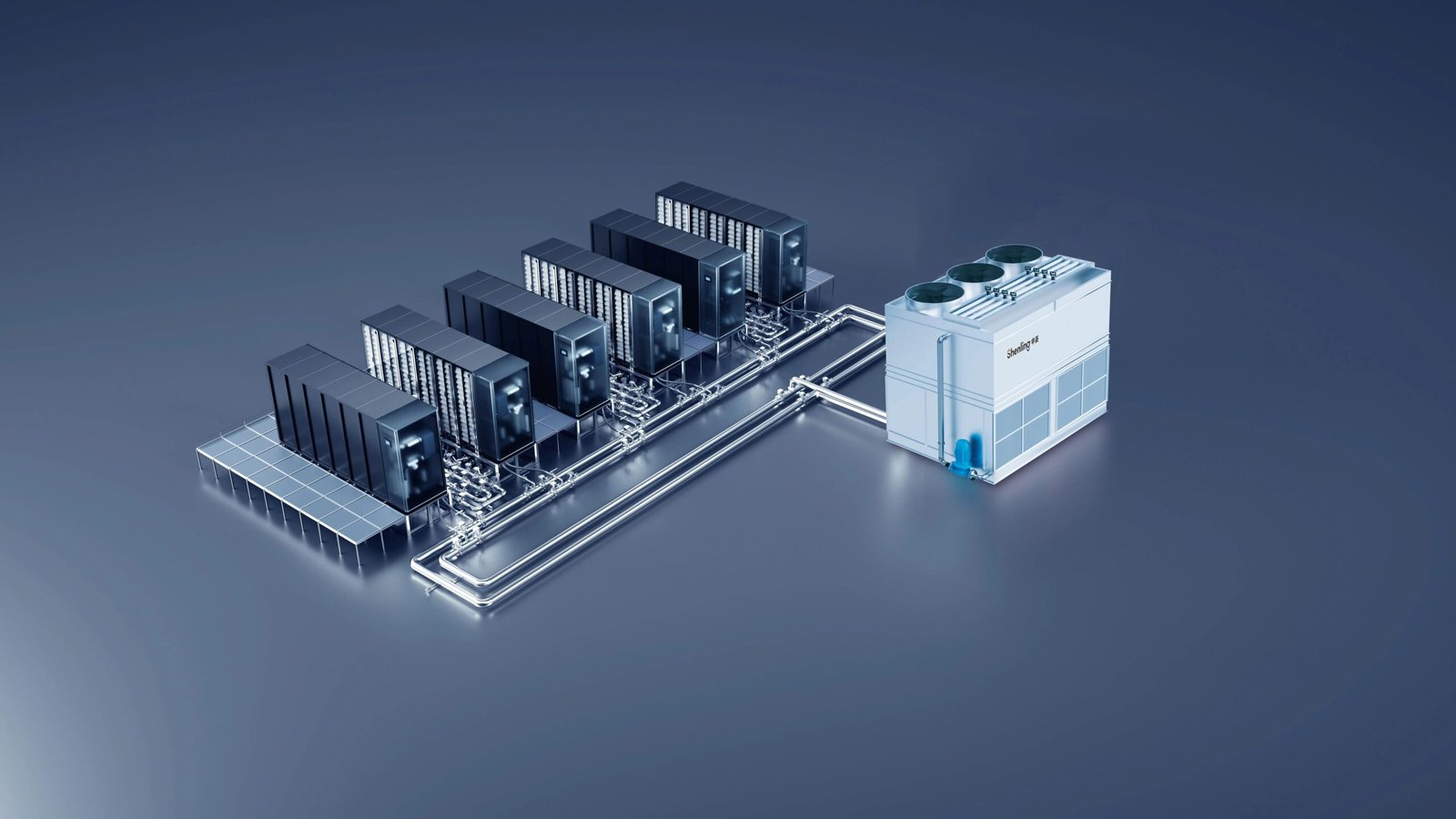
A Cooling Distribution Unit (CDU) is a skid-mounted thermal transfer assembly engineered to mediate controlled heat transfer between two hydraulically segregated fluid circuits. Beyond its fundamental function as a heat exchange interface, the CDU integrates circulating pumps, process instrumentation and closed-loop control subsystems to deliver precise, repeatable thermal regulation for compute infrastructure. This whitepaper articulates CDU operating principles, component-level design logic and qualified application boundaries.
1.2 Rationale for CDU Deployment
The CDU architecture enables hydraulic isolation between thermally dissimilar fluid loops while establishing decoupled cooling distribution networks. The primary circuit interfaces with the site Facility Water System (FWS), whereas the secondary circuit constitutes the Technology Cooling System (TCS), custom-formulated and instrumented exclusively for IT cooling loads. The heat exchanger forms a non-permeable hydraulic barrier, decoupling pressure envelopes and temperature setpoints between the primary and secondary sides. Fueled by widespread adoption of AI accelerators and high-power-density GPUs, the market demand for direct liquid cooling has escalated materially. Although air cooling remains pervasive within legacy deployments, its thermal dissipation ceiling is incompatible with contemporary high-wattage rack requirements. Most next-generation data centers will adopt hybrid cooling topologies that combine liquid and air cooling to holistically manage facility ambient conditions and IT thermal loads.
2. Core Components
2.1 Centrifugal Pumps
The pump acts as the hydraulic prime mover of the CDU, imparting motive force to coolant within the TCS secondary loop and delivering the design head required to overcome cumulative hydraulic resistance induced by cold plates, distribution manifolds and heat exchangers, thereby sustaining the nominal flowrate mandated for server waste-heat abatement. CDU pump specification is an application-specific engineering exercise. While conformance to the design operating point (flowrate vs head) constitutes the baseline requirement, supplementary performance attributes demand rigorous technical evaluation: hydraulic and motor efficiency, footprint optimization, speed-modulation capability, mean time between failure (MTBF), scheduled maintenance cadence and whole-of-life total cost of ownership (TCO).
Energy Efficiency
Pumps seldom represent the dominant electrical load within a data center; nevertheless, their continuous-duty operational profile renders them a material contributor to site PUE. Optimization of pump subsystem efficiency is therefore a critical lever to elevate the overall thermal system coefficient of performance (COP). Aggregate pump efficiency is governed by a coupled set of design variables: motor efficiency grade, hydraulic profile efficiency, mechanical power transmission architecture between motor and impeller, and the degree of motor rating matching against the expected operating envelope.
Motor Efficiency
CDU pumps utilize a spectrum of motor technologies, including electronically commutated motors (ECMs), induction motors and permanent magnet synchronous motors. Motor efficiency classifications are codified within IEC TS 60034-30-2, spanning IE1 through IE5 (ultra-premium efficiency class).
High-efficiency motors deliver cascading operational benefits. Reduced stator and rotor losses suppress self-heating, permitting derated cooling fan sizing and attenuated acoustic emission. Lower thermal loading on bearing grease mitigates thermally induced lubricant degradation and extends bearing service life. Reduced heat rejection also curtails parasitic thermal load inside the CDU enclosure, enhancing subsystem reliability and steady-state performance. Additionally, high-efficiency motor variants support full-shaft-power operation at elevated ambient temperatures without mandatory electrical derating.
Hydraulic Efficiency
Hydraulic efficiency carries equivalent design priority: all internal hydraulic losses are converted directly into sensible heat absorbed by the heat transfer fluid, which must subsequently be rejected through the thermal circuit. Accordingly, pumps shall be selected such that the majority of operating dwell occurs in proximity to the Best Efficiency Point (BEP). Continuous operation far offset from the pump performance curve precipitates efficiency degradation, elevated power draw and excess thermal burden imposed upon the cooling loop.
Torque Transmission
The mechanical interface for torque transfer between motor and impeller exerts substantial influence on aggregate system efficiency. Magnetically coupled sealless pumps deliver zero dynamic leakage but incur non-trivial power dissipation, frequently at the kilowatt scale, which is dissipated directly into the process fluid. These losses originate predominantly from eddy-current induction across the isolation containment shroud; loss magnitude is a function of magnet alloy specification, shroud material and wall thickness. By comparison, mechanically sealed shaft pumps demonstrate materially lower transmission losses and constitute the preferred high-efficiency option for CDU installations.
Reliability
Pump reliability denotes the capacity to preserve design performance across extended service lifecycles with minimal unscheduled downtime and unplanned intervention. Within data center cooling, industrial process and HVAC contexts, pump reliability directly governs platform uptime, operational resilience and lifecycle capital and operational expenditure. Attainment of high reliability necessitates robust mechanical engineering for structural integrity, thermal stability and long-duration operational survivability. Critical subassemblies including bearings, shaft seals and impellers must be engineered to withstand continuous cyclic loading, elevated fluid temperatures and the inherent chemical reactivity of propylene-glycol-based heat transfer fluids. Material compatibility qualification for all wetted components is mandatory to preclude premature corrosion, erosion, permeation or leakage-triggered outages.
Pump Performance Curves
Pump characteristic curves form the foundational hydraulic specification tool. These graphical datasets map pump behavior across variable flowrates and quantify the interdependency between volumetric flow, developed head, efficiency, power consumption and Net Positive Suction Head Required (NPSHr). Curve analysis enables engineers to localize the BEP, validate adequate suction margin to avert cavitation, and confirm stable operation within the system hydraulic envelope. When superimposed upon the system resistance curve, which integrates frictional losses, static head and minor losses, the pump curve resolves the steady-state operating point where pump delivery matches system demand. This renders pump curves indispensable not only for initial equipment selection, but also for energy optimization, impact assessment of circuit reconfiguration and predictive performance diagnostics throughout the pump service life.
Pump Architectures Deployed in CDUs
A range of centrifugal pump variants may be specified for CDU integration, subject to thermal duty, pressure rating and layout constraints. Centrifugal topologies remain the dominant selection owing to mechanical robustness and inherent suitability for continuous steady-state operation. Fluid is introduced axially into the impeller eye; rotational kinetic energy imparts velocity and pressure as fluid migrates radially toward the impeller periphery. This architecture yields pulse-free laminarised delivery and tolerates outlet throttling without hardware damage, rendering it highly compatible with dynamically variable compute loads.
CDU centrifugal pumps are differentiated by core construction attributes: stage configuration (single-stage for moderate head; multistage for high-pressure regimes), mounting orientation (horizontal for service accessibility; vertical for footprint compression and enhanced NPSH margin), and port geometry (end-suction design with axial inlet and radial discharge; inline design with collinear suction and discharge nozzles to simplify piping routing).
Horizontal End-Suction Pumps
Horizontal end-suction pumps are widely specified for CDUs by virtue of simple construction, proven field reliability and maintainability. The pump shaft is horizontally oriented; fluid enters axially through the suction nozzle and exits radially via the discharge port. This layout facilitates straightforward piping integration and permits service intervention on motor and hydraulic assemblies without breaking primary pipe joints. Key application merits include compact rigid construction, stable hydraulic characteristics, high efficiency across low-to-moderate head bands, and broad supply-chain availability that simplifies spare-part logistics and interchangeability. These pumps typically exhibit favourable NPSHr margins under standard CDU working fluids such as PG25 and support customized impeller and motor trim to match circuit-specific thermal requirements.
Vertical Inline Multistage Pumps
Vertical inline multistage pumps are the preferred selection where elevated differential pressure is mandated. Suction and discharge connections are collinear, allowing direct insertion within the piping run to minimize footprint and streamline skid layout. Series-stacked impeller stages develop significantly higher head than functionally equivalent single-stage alternatives while retaining the low-pulsation flow profile required for precision thermal control. Principal advantages include sustained high efficiency under high-pressure setpoints, minimal space claim, low acoustic signature and consistent performance across variable load profiles. The inline configuration reduces demand for complex pipe support structures and can improve NPSH margin within suction-limited installations.
Sealless Zero-Leak Pump Variants
Conventional pumps deploy mechanical shaft seals, which rely on a thin hydrodynamic lubricating film formed across mating seal faces to achieve sealing. While functionally effective, this interface permits trace controlled leakage as an intrinsic operational characteristic. Leakage magnitude is modulated by system pressure, fluid viscosity and seal-gap geometry.
It is important to note that PG25 (25 vol% propylene glycol, balance deionized water) contains a high water fraction that evaporates rapidly; propylene glycol also evaporates at a reduced rate. Macroscopic liquid leakage is therefore extremely rare within operational fleets. Apparent surface residue is typically precipitate of dissolved minerals or fluid additives rather than bulk coolant. Cumulative field experience across large-scale deployments confirms that micro-leakage may manifest, yet evaporative dynamics and seal hydrodynamics generally render such leakage non-visible.
Where a hermetic zero-leakage design is a hard requirement, multiple qualified alternatives exist. Magnetically coupled centrifugal pumps, available in both end-suction and inline configurations, represent the most established sealless implementation.
A second alternative utilizes multistage pumps fitted with liquid-cooled stators, wherein the complete pump–motor assembly is encapsulated within a pressure containment sleeve to form a fully hermetic assembly. This architecture can deliver superior energy efficiency by eliminating eddy-current losses endemic to magnetic coupling systems. Bearings are lubricated directly by the process fluid, enabling maintenance-free operation across the design service life.
For in-rack CDU platforms, where vertical rack-unit (U) real estate is a constrained premium resource, canned motor pumps are a dominant specification. A canned motor pump is an integrated hermetic assembly wherein pump and motor share a common pressure boundary and coaxial shaft. Impeller and rotor are rigidly mounted upon the same shaft, eliminating mechanical seals, flexible couplings and precision shaft-alignment requirements. Process coolant traverses the rotor chamber, which is hydraulically segregated from stator windings by a thin non-magnetic containment can, establishing a static hermetic barrier between the fluid domain and electrical domain with zero dynamic sealing interfaces.
Application Guidance for In-Rack CDU Pumps (Jonas, Brinkmann)
Within in-rack CDU designs, every vertical rack unit carries significant layout constraint, establishing canned motor pumps as the mainstream selection. These units integrate pump and motor upon a single common shaft: the impeller and rotor rotate synchronously, eliminating mechanical seals, flexible couplings and precision alignment overhead. A thin non-magnetic rotor can segregates the wetted rotor cavity from stator windings, delivering a permanent static isolation boundary with no dynamic seal points.
A controlled slipstream of the circulating fluid is diverted internally to absorb motor thermal losses and provide bearing lubrication before rejoining the primary impeller flow path. This self-contained cooling and lubrication circuit obviates external cooling fans and grease-lubricated bearing arrangements, removing grease replenishment and oil-level surveillance requirements. A portion of motor electrical losses is rejected directly into the coolant stream rather than the surrounding rack air. This trait is often advantageous for in-rack CDU deployments as it reduces heat rejection to the rack ambient; nonetheless, this parasitic thermal load must be explicitly incorporated into secondary-side thermal budgeting and hydraulic design.
These attributes carry high relevance for liquid-cooled IT infrastructure. Elimination of the shaft seal removes one of the dominant root-cause leakage failure modes — a critical risk mitigation strategy for pumps co-located adjacent to energized IT hardware. With all rotating components enclosed and no cooling fan, vibration and acoustic emissions are attenuated. The monolithic compact form factor is compatible with the shallow chassis profiles typical of in-rack CDU hardware, and the sealless architecture supports elevated MTBF and reduced scheduled maintenance. The design tradeoff is a moderate efficiency penalty originating from eddy-current dissipation within the containment can and fluid shear losses across the rotor annular clearance.
Pump Motor Drives
Fixed-speed induction pumps operate synchronously to grid frequency (50 Hz / 60 Hz). Variable-speed regulation is a primary efficiency tuning vector. Motor drives supply conditioned power and modulate rotational velocity to adjust pump discharge pressure and volumetric delivery. Variable Frequency Drives (VFDs) modulate induction motor speed by adjusting AC output frequency. ECM drives achieve speed regulation via DC bus voltage modulation. VFD-equipped motors may be operated above nominal grid frequency within certified design limits. Drives support multiple control paradigms: set-and-forget regulation, pressure feedback, temperature cascade control or host SCADA orchestration. As an illustrative example, the CDU master controller may command the drive to ramp rotational speed by 5% to converge upon a prescribed process setpoint.
Drive packaging formats include discrete VFD–pump combinations and integrated pump–drive modules (either monolithic single-skid construction or separable subassemblies).
2.2 Heat Exchangers
Brazed Plate Heat Exchangers (BPHEs)
A brazed plate heat exchanger is a compact high-effectiveness thermal device fabricated from corrugated austenitic stainless steel plates joined via brazed joints to facilitate sensible heat transfer between two fluid streams. Typical footprint ranges from 80 to 350 in²; total heat transfer area scales proportionally with plate count.
BPHE integration within CDUs delivers key benefits: minimal footprint, high thermal effectiveness, modular reconfigurability, hermetic construction and intrinsic self-cleaning characteristics. BPHEs consistently outperform competing thermal technologies on metrics of cooling capacity per unit heat transfer area (kW/HTA) and cooling capacity per unit mass (kW/kg). Highly turbulent internal flow promotes fouling resistance and reduces maintenance intervention. Deployment envelopes extend from sole heat-exchange hardware within in-rack CDUs through to parallelised arrays of up to three BPHEs for in-row CDU platforms with thermal ratings up to 2.5 MW.
2.3 Control Subsystem
1. Programmable Logic Controller (PLC)
2. Application-specific dedicated controller
3. Electromechanical relays
4. Power contactors
5. Multi-voltage power input configurations (AC / DC)
6. Integrated Power Distribution Unit (PDU)
2.4 Filtration Package
High-grade particulate filtration is an essential design requirement for liquid-cooled data centers, particularly deployments incorporating cold plates and microchannel heat sinks. These precision thermal hardware elements demand chemically stable, particulate-free coolant to preserve long-term thermal performance and mitigate progressive fouling degradation. High-efficiency filters are specified to remove fine particulate contaminants with validated capture efficiency, typically utilizing absolute-rated fixed-pore filter media. Performance is quantified by beta ratio, the industry standard metric defining fractional particle capture efficiency at a calibrated particle diameter.
Accepted high-efficiency performance benchmarks:
1. Beta 1000 (99.9% capture efficiency)
2. Beta 5000 (99.98% capture efficiency)
3. Beta 10000 (99.99% capture efficiency)
For liquid cooling circuits feeding microchannel cold plates, a minimum Beta 5000 rating at the critical particle cut size is generally mandated to suppress fouling and channel occlusion risk.
Filters deploy disposable cartridges or filter bags for fine contaminant removal, targeting particulates below 25 μm alongside biological colloids. Filter media is frequently multilayer polypropylene, engineered to balance capture efficiency and service life. Given fine-particle retention and single-use design, filters are commonly manifolded in parallel to elevate allowable flowrate while constraining differential pressure rise. Side-stream polishing filtration is also implemented, whereby a fractional slipstream is diverted through the filter medium to gradually reduce bulk-fluid contaminant loading over time. These filter elements are consumable and not intended for cleaning or reuse.
Direct-to-Chip (DTC) liquid cooling relies upon microchannel cold plates featuring ultra-narrow flow passages. Flow-path occlusion can induce catastrophic silicon over-temperature and permanent component failure. Filtration cut size must therefore be substantially finer than the minimum channel dimension, and coolant quality governed under stringent continuous monitoring protocols. Filtration architecture for microchannel cold plate loops must be engineered and specified against these rigorous reliability constraints.
Strainers
Strainers provide upstream protection for downstream capital equipment by intercepting macro debris and large particulates, safeguarding heat exchangers and cold plates to sustain thermal conductance. Configurations include in-line, angle and Y-type strainers. Strainers are sized for particulate capture ≥25 μm, operating as a pre-filter complementing fine filtration for sub‑25 μm contaminants. Retention media includes wedge wire, perforated tubes and woven screen mesh. Strainer baskets are removable, cleanable and reusable.
Critical specification parameters for strainer selection are design flowrate, maximum operating pressure, screen surface area and particle morphology. Flow magnitude and mesh aperture dominate pressure drop across the assembly. Parallel strainer installation distributes flow to maintain low differential pressure. Larger available screen area elevates dirt-holding capacity and extends service intervals between cleaning cycles.
2.5 Valving Assembly
1. Two-way valves: Sanitary stainless steel butterfly valves, encapsulated or non-encapsulated sanitary ball valves
2. Three-way valves: Encapsulated sanitary three-way ball valves for flow diversion and switching logic
3. Check valves: Enforce unidirectional flow; typically installed immediately downstream of the pump discharge flange
2.6 Fill, Drain & Vent Interfaces
The TCS piping circuit shall incorporate dedicated ports for fluid charging and controlled draining. Charging connections are mounted locally upon or adjacent to the CDU, with interface sizes ranging down to garden-hose quick-disconnect fittings. Concurrent air-elimination infrastructure is mandatory alongside fluid filling. Automatic air vents (also termed boiler vents) constitute the primary technology: these devices vent entrained non-condensable gas while preventing bulk coolant escape.
Minor droplet entrainment or spattering during venting is classified as normal operational behavior. Some vents discharge air directly to atmosphere via precision orifices or threaded ports; alternative designs incorporate hose barbs to route incidental liquid carryover to containment drainage. Air vents shall be distributed strategically across the full TCS loop, with priority placement at all hydraulic high points. Air purging is critical to reduce dissolved and entrained gas fractions. Gas is liberated during initial filling, commissioning flushing and equipment tie-in. Additional outgassing persists through the first month of steady-state operation and is managed by this vent network. Vents support manual isolation or continuous automatic venting modes.
2.7 Temperature Instrumentation
Multiple sensor families are deployed within CDU assemblies; Resistance Temperature Detectors (RTDs) and thermocouples are the dominant selections. Sensors may be surface-bonded externally to pipework, installed within sealed thermowells immersed in the fluid stream, or fitted for direct wetted contact — though direct immersion is less prevalent within CDU instrumentation suites. Sensors deliver process feedback for control logic and are positioned on supply, return and internal CDU branches, with optional remote sensing nodes to enhance transient response.
For instance, return temperature may be sampled proximate to the last IT thermal load within the loop rather than at the CDU return inlet, delivering earlier detection of thermal transients. Faster sensing enables the CDU control stack to respond more rapidly to dynamic workload fluctuations.
Temperature measurement forms the backbone of thermal management for efficiency and asset protection. Supply–return delta-T monitoring enables real-time heat-load quantification and dynamic pump speed trimming. This maintains CDU surface and fluid temperatures above facility dew-point temperature to suppress condensation risk. Continuous fluid temperature surveillance triggers alarm interlocks and flow modulation to prevent semiconductor over-temperature failure. Delta-T trending across heat exchangers also supports predictive diagnostics for fouling and thermal performance degradation.
2.8 Pressure Instrumentation
Pressure transmitters constitute a core sensing layer for CDU operation. Deviations in differential pressure provide leak-detection telemetry, and calibrated delta-P measurements are utilized to infer volumetric flowrate. Sensors also monitor pump discharge pressure for closed-loop speed regulation and feed predictive maintenance workflows. Combined temperature-and-pressure transmitters reduce component count, wiring complexity and integration labor.
2.9 Flow Transmitters
Flow transmitters continuously monitor circulating coolant flow to preserve stable, efficient and safe liquid-cooled data center operation. They are deployed on both primary facility circuits and TCS loops, including in-rack and in-row CDU variants. Flow range, pipe nominal diameter and process envelope govern sensor selection. Measurement accuracy and permanent pressure loss are primary evaluation criteria; a target accuracy better than ±1% Full Scale (FS) is recommended. Excessive pressure drop increases pump shaft power and degrades system COP; low-loss designs (e.g., <50 mbar at 40 L/min) are therefore prioritized. Integrated temperature sensing within flow transmitters consolidates thermal monitoring and reduces hardware and installation overhead.
2.10 Level Transmitters
Level transmitters continuously track coolant inventory within the expansion tank. Low-level detection provides an early interlock to prevent pump dry-running and cooling loss prior to air ingress into the hydraulic circuit. High-resolution level telemetry enables automated fill/drain sequences, alarm annunciation and protective interlocking to sustain safe and stable liquid-cooled operation.
2.11 Coolant Quality Monitoring Package
1. pH measurement
2. Electrical conductivity
3. Particle counting and particulate sizing analysis
4. Refractive index
2.12 Expansion Tanks
The expansion tank fulfils four foundational functions within CDU hydraulic design:
1. Thermal volume compensation to accommodate fluid volumetric expansion induced by temperature swing
2. Static system pressure stabilization and setpoint pressurization
3. Gas–liquid phase separation and continuous degassing
4. Fluid inventory buffering for makeup and drain operations