


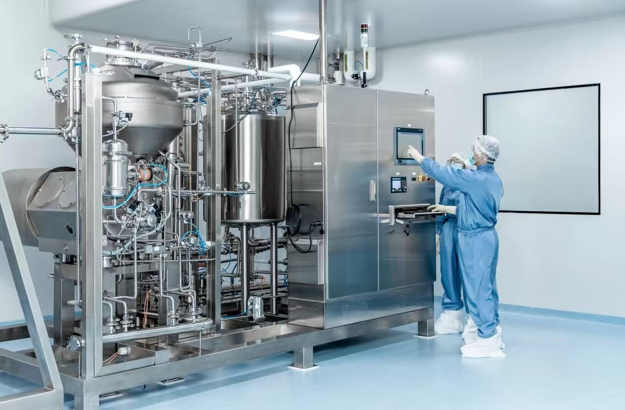
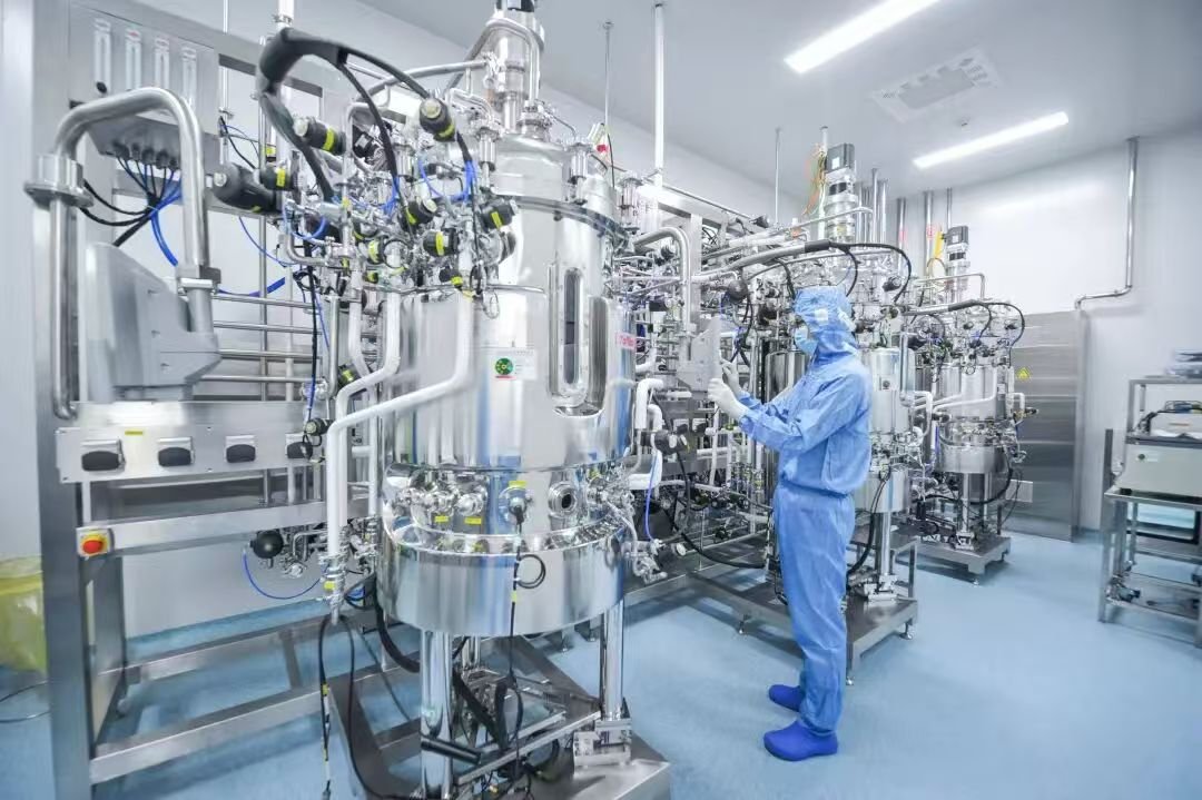
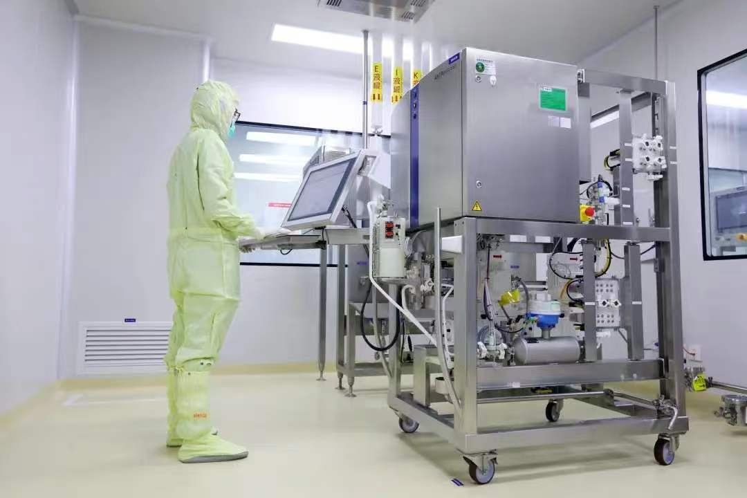
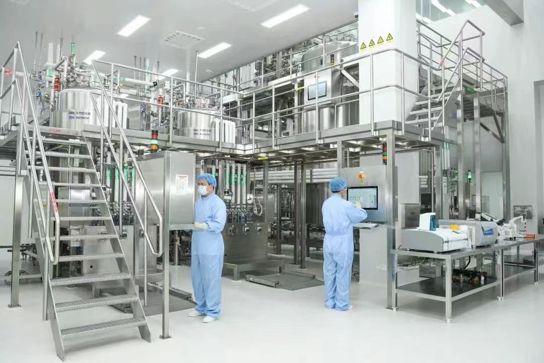
With the scale of operation for the upstream chosen to fulfil the mass demand per batch/campaign, the scaling up of a downstream process becomes the next task. Taking as an example a typical process for purification of monoclonal antibodies, it consists of three main types of unit operations: (1) liquid/solid handling; (2) filtration; and (3) chromatography. The liquid handling includes storage, transfer, and mixing of process solutions, including product pools, buffers and cleaning solutions. The solid handling specifically refers to handling of biomass by centrifugation. The filtration includes all the procedures where either filters or membranes are used, and can be further divided into normal flow filtration (NFF) and cross-flow or tangential flow filtration, (CFF) and (TFF), respectively. The chromatography includes both slurry (batch) and packed-column separations that are either based on interactions, or size, or both. Membrane chromatography is also included in this category.
Following is a brief description of guidelines for scale-up for each of these unit operations. And, although these rules are relatively simple, it is important to bear in mind that these are guidelines and that some detailed studies should be always performed to ensure that no loss in product activity and/or in process yield are encountered at the final scale due to unaccounted for phenomena.
Liquid Handling
Liquid handling operation includes liquid storage (buffer preparation and hold, and in-process hold-up steps), liquid transfer, and mixing. Among these, only liquid transfer will not be covered here, but from the scale-up perspective, care must be taken that no extensive shear stress is introduced during product-containing solution transfer to avoid unnecessary yield losses due to antibody unfolding or aggregation. It has been suggested that a shear rate as low as 10,000s–1 could induce unfolding of an mAb.
Intermediate Product Hold Vessels
The simplest approach to scaling up hold vessels in a downstream process is to use the concept of concentration. By setting a minimum final concentration of a product in a tank at any stage of the process, the maximum operating volume for each tank can be easily calculated. The same approach can also be used to identify bottlenecks in an existing facility. The actual size (volume) of a vessel will be larger, as the operating range of volumes for typical tanks is around 80%–90% of the total tank volume. In cases where a product hold step requires adjustment of liquid composition and this cannot be done in a dynamic mode using a static mixer (in-line adjustment), the scale-up exercise must account for extra volume needed and for effects related to mixing efficiency as variation in local composition within a vessel can affect product quality. For instance, during pH adjustment prior to the post-Protein A low-pH virus deactivation step, a local decrease in pH can cause irreversible aggregation of an antibody. Similarly, product solutions may require agitation to ensure a homogenous mixture is achieved for further unit operation processing (e.g., loading onto a chromatography column). Agitation speeds and the shear impact that they may/may not have on the product within the solution would need to be investigated and considered. Additionally, temperature needs of a specific step should also be considered. Although parameters at the small scale would help determine the operational temperature for processing, care must be taken for product stability, should the product be required to be held for elongated periods, such as overnight, due to shift schedule restrictions, or in the case of unit operation failure or an emergency shut-down situation.
In recent years, use of single-use bags for buffer distributions and intermediate product hold has changed the way processes are designed. It has been shown that significant savings can be realized when replacing a stainless steel tank park with single-use bags. Due to limitations in available bag sizes, there is a certain limit on the scale at which the single use bags can be used. Currently, the single-use bags used in manufacturing of biologics range from 1 to 3000L in volume. One approach to increasing the use of single-use bags for larger-than-available scales is to use several smaller bags to reach the total volume required, linked together with a manifold to facilitate transfer. However, this approach would need to be evaluated based on the increased consumable, labor, and space management that it would require as opposed to the use of a single large re-usable tank. Care must be taken to ensure the selected volume of the bag can accommodate the mixing, temperature, and solution monitoring needs of the process. As the purification process progresses, the product becomes more concentrated, and hence volume reduces. As such, product hold vessels need to accommodate these reduced volumes. In general, the industry trend is to utilize single-use technology at smaller scales; currently only limited mixing technology exists for smaller 2D single-use bags (1–20L). Either rocking technology mixers or pump recirculation, where a single-use pump is used to recirculate the product within its hold bag, can be utilized at this scale. Recirculation options should be evaluated for their impact on the product in terms of any temperature increase or shear. Temperature control could also be problematic for 2D single-use bags because these are typically not available in a jacketed format. However, newer technology, such as single-use heat exchangers may be utilized to resolve this issue.
Solution Preparation Vessels
The scale-up of a solution preparation vessel becomes a little bit more complicated because a mixing process is involved. Generally, these are limited to solution preparation of buffer and cell culture media in which dry raw material components are added to water or in which two or more liquid solutions are added together. From the perspective of mixing efficiency, the criterion for scale-up are geometry, impeller speed, and mixing time. A successful scale-up should maintain these factors at the pilot and full scale; however, this is rarely practical with any significant scale change. From a practical mixing scale-up perspective, a concept that greatly simplifies design calculations is geometric similarity. Geometric similarity means that a single ratio between small scale and large scale applies to every length of dimension. With geometric similarity, the only remaining variable for scale-up to large-scale mixing is the rotational speed of the impeller, which, in many cases can be made fairly similar to the respective speed at a smaller scale. However, even with geometric similarity, scaleup will result in less surface per volume because surface area increases as length squared and volume increases as length cubed. For this reason, vessel shape has also been a significant area of consideration in selecting solution preparation unit operations. Larger stainless steel vessels have been traditionally cylindrical in shape, owing to the mechanical stability and footprint considerations that come with scaling up their use at large volumes (5000L and greater). Newer, single-use solution preparation devices have explored different vessel geometries, limited as they are to smaller volumes (up to 5000 L presently). The authors concluded that the lateral cuboid tank shape with dual impeller was very good at dispersing the solid particle additions with negligible settling compared with other tank shapes. Generally, such single-use mixing systems have tended to be more of a lateral cuboid shape, not just for mixing optimization, but also to facilitate bag exchange. The intended technology to be used at large scales should be considered at the process development stage to ensure the appropriate scaling parameters are chosen.
The traditional way of solution preparation is through a batch-wise manner that involves off-line quality control measures to ensure solution accuracy with potentially large-volume solutions. One possibility of increasing the productivity and reducing the footprint of such a solution is the consideration of the use of concentrates and in-line dilution. In-line buffer dilution involves the use of concentrated buffer solutions that are diluted with water, pH-adjusted, and mixed as they are sent to the downstream processing step. Because concentrated solutions are used, much smaller storage equipment and less space are required. For instance, it has been shown that using buffer concentrates and static mixers could reduce: (i) tank sizes two fold, (ii) number of buffer preps and CIP operations per batch by more than 30%; and (iii) labor requirements by 31%.
It should be noted, however, that in-line buffer mixing can be challenging, because the buffer solutions must be well mixed and meet tight specifications for pH, temperature, and other critical parameters when they are delivered to the process step. Because of this, strict control over the solutions is necessary. The consequences of poor mixing can be significant and range from reduced process performance to the production of out-of-specification products.
Solids Handling (Solids Removal)
Centrifugation
Separation of solids in a monoclonal purification process is limited to handling of biomass during the primary recovery of the antibody. Most industrial processes use disc stack centrifuges, as these apparatus are scalable, perform continuous operation, and have a capacity to handle a wide variety of feed stock. Typically, secondary clarification using a depth filter after centrifugation is required prior to further downstream processing. Efficiency of the centrifugation step depends on the solids volume fraction, the effective clarifying surface (V/D), and the acceleration factor (ω2r/g). Typically, accelerating factors of 1500g are used for harvesting cells. The product of these two factors (ω2rV/gD) is called the sigma factor (Σ) and is used in scale-up calculations. The sigma factor represents the equivalent area of the centrifuge and is unique for each disc stack centrifuge and the angular velocity. For continuous operation, the ratio between flow rate through the centrifuge, Q, and the sigma factor should be kept constant during the scale-up. The sigma factor can also be used to scale disc stack centrifuges from a lab bottle centrifuge, by replacing one of the flow rates in the above-mentioned ratio with centrifuged volume divided by time of the centrifugation. However, keeping the ratio of Q/Σ constant may still lead to inadequate operation at large scale due to hindered settling and the presence of sub-micron particles generated during the centrifugation process itself. These particles are formed from cell and cell debris upon exposure to high shear (see discussion on the effect of mixing on bioreactor performance) and are removed from the centrifuge in the concentrate stream. In addition, shear damage can cause release of proteases that could affect stability of the antibody.
Depth Filtration
Although the use of a centrifuge is fully accepted, its application is most suited for primary harvest activities with a high solids content or that require the processing of large volumes. For pilot to mid-scale operations (e.g., up to 2000 L), depth filtration has recently been utilized instead of centrifugation for the separation of cell debris and other solids in extracellular mammalian culture applications. Depth filters used in bioprocessing are typically composed of a fibrous bed of cellulose or polypropylene fibers along with a filter aid (e.g., diatomaceous earth) and a binder that is used to create flat sheets of filter medium. The filter aids provide a high surface area to the filter and are sometimes used by themselves in clarification applications. An additional charge can be imparted to some depth filters, either from the binder polymer, or from other charged polymers incorporated into the filter. Sometimes, a microfiltration membrane with an absolute pore size rating is integrated into the depth filter sheet as the bottom layer. Porous depth filters can retain particles in their tortuous flow channels to a level that size-based screening alone cannot achieve.
For process-scale applications, depth filters are often fabricated into cells consisting of two layers of filters separated from each other such that flow occurs from the outside into the space between the layers and is then collected. Multiple cells can be stacked into a housing in which pressure is used to drive flow through the assembly. Depth filters are usually singleuse devices that enable a reduction in the extent of process validation required for their use in biopharmaceutical applications. Scale-up of depth filtration is typically achieved by keeping filtration flux.
One issue with the use of filtration for solids separation is that it can be prone to membrane blocking, increasing the pressure of the process. Given this issue, it is typical to have two stages of depth filters for the filtration of a mammalian cell broth, each stage reducing in porosity. Scaling up at constant flux and often keeping filtration time constant, however, lead to a linear increase in the filtration area required as the volume to the process increases. At very large volumes, the membrane area required for filtration becomes infeasible, and in this case, a centrifuge may be employed as a precursor to the depth filter as previously mentioned.
An often cited issue with depth filtration is the significant membrane flushing volume (typically with water for injection or purified water) required as a precursor to the filtration itself. This is to ensure any contaminant particles existing within the membrane itself are flushed from the system. For certain membranes, this may require flushing with at least 100L/m2 of water prior to filtration. In most cases, an additional buffer flush may be undertaken after water flushing to equilibrate the membrane, particularly those that are charged. Sizing of a depth filtration step for the manufacturing scale therefore should account for these ancillary steps to ensure the facility can accommodate the water flushing needs of the system.
Membrane Filtration
Membrane filtration is one of the most frequently used unit operations in biopharmaceutical manufacturing. Filters are used for depth filtration, ultrafiltration, and diafiltration applications, for sterilization, gas, and virus filtration. In a typical monoclonal antibody purification process, dead-end filtration accounts for more than 12% of the total purification process cost. Hence, properly designed/optimized filtration steps can improve economy of the manufacturing process. However, any optimized process will underperform if the filter performance changes with scale.
Scalingup filtration steps from a laboratory scale to a production scale system poses several challenges not only related to the change in size, but also to change in filter format (disk versus pleated) and mode of operation (in parallel or in series). The challenges include: (i) limited access to representative material due to high production costs and/or limited production runs; (ii) surrogate fluid may not be representative of the actual process fluid; (iii) small-scale studies may not represent the conditions under which the filtration occurs in the manufacturing scale; (iv) laboratory scale filter elements used for testing may not be predictive of large-scale filter capacity. To overcome these challenges, so called “safety factors” are used to ensure successful operation at scale. Safety factors can vary depending on the type of filtration step. These factors will be also briefly discussed later in the text.
From the scale-up perspective, filtration can be divided into NFF (dead end) and tangential flow filtration (sometimes referred to as cross-flow filtration). The dead-end filtration will include bioburden reduction filtration, virus filtration, and depth filtration, while cross-flow filtration will include ultrafiltration/diafiltration, and microfiltration applications.
Normal Flow Filtration
Dead-end filtration applications can be divided into flux-limited and capacity-limited cases. Filtrate flux depends on membrane permeability (a function of pore size distribution, porosity, and thickness), and on the solution properties (e.g., viscosity, density, and temperature). Capacity, on the other hand, is related to the rate of fouling of the membrane. Fouling will depend on solution composition, as well as on process conditions. Fouling increases pressure over the filter. Thus, should the filtration process be operated at constant pressure, the flow rate will need to be decreased to account for the increased fouling, and as such, flux will decrease as process time increases.
Design of a filtration step always starts with a decision over which type of membrane will be most effective for a given filtration task. If heuristic information is not available, screening of different filters is the first step in designing a filtration step. Typical experiments involve determination of flux, filter capacity, and step yield for a given feed stream. Scalingup of a filter used in an application where the filtration is flux limited is fairly simple because of the assumption that filter performance scales linearly with filtration area is typically correct and the filter is sized based on the total volume to be processed and the processing time available for the filtration.
Regardless of the method used to find out filter capacity, the scale-up is accomplished by assuming that between 50% and 80% of filter capacity (Vmax) scales linearly with the filter area. Based on this assumption, a minimum filtration area necessary to accomplish a given filtration task within the time specified when operating at a given constant pressure can be calculated. With the minimum filtration area known, the final size of the filtration unit is determined by applying a safety factor to account for feed and membrane variability. Typically a safety factor of 1.5 is used, but larger safety factors can be applied if a more variable feed stream, such as harvested cell culture fluid, is used. Because the normal flow filters are usually available in finite size cartridges, the final sizing of a filtration step must account for the available cartridge configuration, including the filter housing aspect.
The filter housings typically used in manufacturing are designed to accept either single or multiple cartridges. These cartridges come in standard lengths of 10, 20, 30, and 40 in., and are generally slightly less than 3 in. in diameter. Among many types of housings available, the most common is the T-style, which is designed for installation into fixed piping systems, and is well suited for installation in filtration skids.
Virus Filtration
When discussing scale-up of NFF operations, most attention should be paid to virus filtration, as it is one of the most important and costly operations during purification of a monoclonal antibody. While in principle, scale-up of virus filters is done using the same basic strategy as for sterile filtration, it is advisable to extend the capacity study beyond the expected manufacturing scale by a factor of 1.5 to 2 to deal with feed stream and membrane lot-to-lot variability. Furthermore, because of relatively low fluxes achieved with the current virus filters and steadily increasing batch sizes, it can be expected that several virus filter elements operating in parallel are necessary. Generally, there tends to be low pressure and high pressure viral filtration technology. Although operating at increased pressures improves filtration flux, line pressures should be minimized due to safety concerns. Further, the use of an adsorptive-pre-filter to bind and thus to remove charged smaller impurities that cannot be removed by a 0.2 or 0.1μm pre-filter could reduce the minimum filter area required up to ten-fold. Care must be taken to avoid yield losses due to product adsorption on the charged filter. The scale-up of virus filtration must also address integrity testing of the filter before and post-processing. Too many cartridges in a single housing can create a challenge from the cartridge integrity test perspective. However, recent analysis showed that from the integrity test perspective, up to 20 filters could be placed in the same housing if the diffusion integrity test is used, which should circumvent the filter integrity issues from most, if not all, virus filtration steps.
Tangential Flow Filtration
Typical tangential flow filtration (TFF) applications include ultrafiltration/diafiltration (UF/DF) processes and microfiltration steps. In TFF, the product stream flows parallel to the membrane surface, that is, in the direction perpendicular to the filtrate flow. The sweeping action of the product stream flow reduces concentration polarization effects, such as build-up of retained solutes on membrane surface, and/or effects related to osmotic pressure. The sweeping action of product stream can be enhanced by introducing secondary flow involving Taylor or Dean vortices. The presence of the cross-flow in TFF units provides a challenge from a scale-up perspective as the hydrodynamic conditions, and thus all physical phenomena related to these, must prevail at different scales in order to maintain the same flux characteristic.
Despite the same basic modus operandi for UF/DF and microfiltration steps, these two applications of cross- flow filtration are rather different. For one, microfiltration is used early in the process train where it can be used for initial harvest of proteins from mammalian, yeast, or bacterial cell cultures, whereas ultrafiltration is used for protein concentration and buffer exchange. Thus, the two applications require membranes with different pore sizes and different cartridge design to accommodate feed streams with different characteristics. Because the feed streams are different, different phenomena need to be considered when optimizing the two applications. On the other hand, the scale-up process is fairly similar, if not the same. As in the case of dead-end/normal filtration, size of a filtration system will depend on the filter capacity defined as the volume of feed that can be processed per unit membrane area before a new membrane needs to be used or the old membrane needs to be regenerated. Depending on whether the filtration is operated at constant flux or constant pressure conditions, this volume will be linked to a moment at which the pressure drop in the system reaches a pre-set maximum value or the permeate flow rate drops to an unacceptable level, respectively. For the latter, as a rule of thumb, the permeate flux at approximately 80% of the maximum mass flux should be selected for stable process operation.
Scale-up of a TFF step can be generally considered simple because membrane cartridges (cassettes or hollow-fibres) are linearly scalable. This linear scalability is achieved by the geometrical similarity of the membrane cartridges at different scales. Geometrical similarity ensures that the scale up, and scale down for process validation purposes, can be based on keeping volume processed per area of membrane constant at different scales without changing process performance. The geometrical similarity relies on two factors: (1) keeping channel length constant and (2) keeping the same hydrodynamic regime within the channels. In combination, these two factors guarantee that trans-membrane pressure, local flux, pressure drop across the channel and protein concentration at the membrane wall are as close as possible at all scales of operation.
With the current cassette design, the flow path is kept constant and the desired membrane area is achieved by increasing a total number of channels per cassette. Linear scaling of hollow fiber cartridges is also achievable, providing the length of hollow fibres is kept constant. In the case of hollow fiber cartridges, equal flow distributions and manifold design are easily achievable, as the filtrate pressure losses are often insignificant, which results in reproducible fluid dynamics conditions within different-scale cartridges.
Sizing of a UF/DF unit to process a specific volume within a given processing time to reach a desired concentration factor and a final composition is performed based on average permeate fluxes measured at process conditions. With the fluxes known, the minimum filter area for a UF/DF step for different processing times can be quickly estimated following the procedure outline. For a given average flux, a ratio between the volume to be processed and the average flux is calculated. The intersect between a desired process time (e.g., ultrafiltration time), TUF, and a line representing the calculated ratio is found. The ordinate of the intersect point provides the minimum membrane area necessary to process the volume in the desired time. Given the increasing protein concentration in the ultrafiltration step and its effect on the filtration flux, this stage is used for filter membrane sizing. The permeate flux and filtration area, once determined, is then used to estimate the ultrafiltration time, tuf. A reverse procedure is used to find the diafiltration time, tdf (i.e., the intersect between the line representing the membrane area and the line representing the ratio between total volume of diafiltration buffer and the average flux is found). The abscissa of the intersect point gives the duration of the diafiltration operation, tDF. The average fluxes for either UF or DF steps are determined by measuring volume of the filtrate collected and the time needed to reach the chosen concentration factor, or to permeate the desired number of dia-volumes.
It should be noted that when highly viscous streams are to be processed, the linear scale up concept can be a challenge, as the typical cassettes used in biomanufacturing were not designed for this type of feed stream. The combination of high viscosity fluids and high flow rates expose any minor shortcomings in cassette construction that may lead to unpredictable effects at a larger scale.
Systems and Filter Cartridges
Different systems configurations are available for various filtration tasks. The systems vary in scale and degree of automation. The minimum configuration of the system should include filter membrane and modules holders, feed pump and pressure, UV sensors for the feed and permeate lines, and a recirculation vessel. In the cases of microfiltration, a permeate pump may be considered. Current systems use components that enable processing at flow rates from 50 mL/min to 1400 L/min, using pipes with diameter from 6 mm to 152 mm, respectively. Cartridge filters and capsules for bioprocess filtration are available from approximately a 0.05 to 36m2 effective filter area in one filter device. For UF/DF applications, different types of membrane modules are available. Most common among these are hollow fiber and spiral wound cartridges, and flat sheet cassettes.
Overall filtration time should be a main consideration for the UF/DF step. Attaining high concentration factors or washing with many dia-volumes requires significant recirculation time, which could have shear impacts on the protein solution and, in some cases, increase the temperature of the solution. If the product solution is deemed temperature sensitive, a jacketed recirculation vessel should be utilized.
One of the important aspects of UF/DF or microfiltration systems should be minimization of yield losses and reduction of dead volume, which reduces wash volumes. From a large-scale process perspective, this is achieved through the use of a final flush with a ~10L/m2 of flush buffer to recover any protein product within the pores of the membrane. The quantity of flush buffer used is critical when UF/DF is used for the final formulation of bulk drug substance at the very end of a process. Here, the final concentration of the product is of importance, and therefore, the volume of flush/recovery buffer utilized must be taken into account. However, the amount of protein recovered could vary, and is likely not predictable. In this case, the designer may consider a second concentration step after flushing to ensure accurate concentration levels are achieved, or over-concentrate the solution in the first place and use the flush to achieve the desired concentration. Another important aspect of scaling up of an ultrafiltration step is related to the system limitations with respect to maximum volume concentration factor and maximum number of dia-volumes beyond which no change in composition can be guaranteed. Thus, it is not recommended that one design processes where volumetric concentration factors greater than 50 will be required for the concentration stage and with dia-volumes of more than 14 for the diafiltration stage.
As a final word in this section, it should be emphasised that determination of optimum membrane and process conditions, including combination of pre-filter and final filter to increase the filter step capacity, relies heavily on empirical testing, and although the filtration data obtained in small-scale experiments could be used for scale-up calculations, it is recommended that the data is used only as an indication of filterability. Pilot scale studies should always be conducted under actual process conditions, preferably using the filter design of the same type as at the final process scale design to ensure successful scale up.
As a leading process-oriented engineering company, Sino Bioengineering delivers professional bioengineering solutions and comprehensive technical services to clients worldwide.
For more products and solutions: https://sinobioengg.com/category/solution/
For more service: https://sinobioengg.com/category/service/