

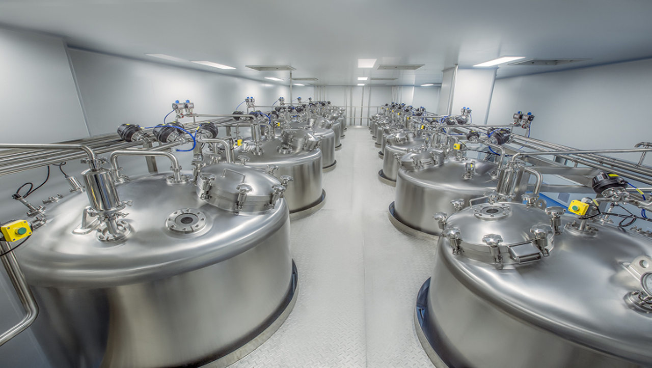
Single-use systems have, in the last decade, become a fully accepted component in biopharmaceutical production. Their uptake has been predominantly in the use of buffer and cell culture media hold vessels, as well as for the growth of animal cell culture. However, their application is limited by scale, and in some cases, maturity of technology. Thus, traditional stainless steel vessels and piping represent the proven alternative to any “gaps” in the singleuse portfolio. The drawback, however, is that the use of product contacting steel surfaces requires rigorous, well defined, and reproducible cleaning in between batches. Reproducible cleaning of product contacting surfaces is critical to prevent contamination of product that could alter its safety, identity, strength, quality, or purity. Any residue of previous production batch is to be washed away completely to avoid cross-contamination.
Generally, biopharmaceutical processes primarily employ aqueous-based cleaning, using alkaline and acid solutions to remove the “soil” or contaminants, returning the equipment to its original use condition. Equipment cleaning regimes are batch-wise in nature, where a defined sequence of steps or phases are undertaken within a particular cycle. A CIP cycle is made of one or multiple phases, described as follows:
Rinse Phase
Rinse water, or solution, is supplied from the CIP unit, and this phase is used to flush the CIP circuit of all free rinsing soil and chemical solutions to waste. The rinse phase may be repeated multiple times during a CIP program as a pre-flush prior to a chemical wash, or after a chemical wash as a post-wash rinse. Although most rinse phases are performed with water, the rinse may also be performed with a base, acid, saline, or solvent solution.
The most common application of a rinse solution is high quality water, but not necessarily the highest quality water in the facility. If there are two water qualities available in the facility, the lesser quality water may be suitable for the rinse and chemical wash phases, with the process quality water being used in the final rinse phase, thus reducing production cost of high quality water in the facility. Typically, purified water is used within the rinse steps, with WFI utilised for the final rinse. The recipe set point for the rinse temperature may require adjustment, heated or cooled, to tailor the phase to the cleaning needs. For example, a heated post-rinse is desirable to improve the solubility of alkaline solutions, reducing the rinse volume required to remove the spent solution.
Gas Blow Phase
This phase uses compressed, filtered gas to clear the CIP supply and process piping to the process equipment being cleaned to enhance a clear transition between dissimilar phases, when necessary.
The gas used is filtered process air. or nitrogen for systems that require an inert atmosphere. A gas blow pressure release step is always included in the phase to allow the gas pressure to dissipate prior to continuing with the CIP program. An intermediate drain phase always follows a gas blow phase to discharge the solution to be blown into a vessel for transfer to waste handling.
Intermediate Drain Phase
An intermediate drain phase is used between CIP phases to actively transfer spent wash and rinse solutions from the circuit boundary to enhance a clear transition between dissimilar phases. The objective is to remove previous rinse or wash solutions from the circuit prior to introducing the next solution. An intermediate drain is recommended after a rinse or chemical wash phase to ensure a clear separation between the previous solution and fresh wash or rinse solution to be supplied.
Chemical Wash Phase
This phase performs the chemical cleaning duty and may be either a single pass through the circuit to waste, or recirculated through the CIP circuit. The chemical wash may be an alkaline or acid solution in aqueous cleaning programs.
The objective of the chemical wash phase is to expose all equipment surfaces within the cleaning boundary to the required physical action, time of exposure at cleaning temperature and chemical concentration to dissolve, suspend, and remove the product soil.
Chemical Selection
The required cleaning chemistry is dependent on the nature of the soil to be removed. For example, if the soil is primarily a biological material made up of carbohydrates, protein, and fat, then an alkaline-based cleaner is suitable for the primary chemical wash phase. However, if the soil load is primarily protein in nature, a hot acid wash may best serve the needs of the equipment to be cleaned.
Commonly used cleaning chemicals include caustic soda, phosphoric and nitric acids, sodium hypochlorite (Hypo), and peracetic acid (PAA). Caustic soda is an alkali typically used at 0.5%–2% volume. It reacts with the fats in the soil and softens it for removal. One downside is that caustic soda is not effective for removing scaling. Phosphoric and nitric acids are used in detergent formulations for scale removal, often at lower temperatures than caustic. These acids must be used with care as they can attack valve and pump seals.
Common CIP chemical solutions are commercially available, for example, CIP 100 (alkaline detergent) and CIP 200 (acid detergent) (Steris Life Sciences), which are typically the first recourse for testing suitability for cleaning.
Final Rinse Phase
The final rinse is performed with the highest quality water available within the facility, meeting the quality of water used for process operations (usually WFI). The objective of the final rinse phase is to flush all equipment surfaces within the cleaning boundary free of all product soil and residual chemical wash solution. The final rinse water should be specified in the User Requirements as either: (i) the highest quality water available in the facility or (ii) the water quality equivalent to that specified for process operation. The termination point for the flush is typically based on CIP return conductivity or resistivity monitoring, or based on supply of a flush volume validated to achieve the required results.
Final Drain Phase (Gravity)
This phase begins by opening all drain valves, with CIP return pumps and equipment gas blanketing “off,” providing for gravity drainage to and from all CIP circuit low points.
The final drain removes, via gravity, the residual rinse at CIP circuit low-point drains prior to concluding the CIP Program. As there are differences in the function, there are also device-positioning differences in the intermediate and final drain. The intermediate drain uses some form of motive force (pumping, gravity, educator assist, or some combination thereof) to actively direct the solutions to waste. The final drain opens all low-point drain valves, and gravity drains off the minimal residual amount of final rinse water or solvent.
The make-up of the CIP cycle must be determined on a case by case basis to be customized for the specific surface soils that need to be cleaned.
Given the complexity of the cleaning cycle, it is challenging to clean unit operations within a biopharmaceutical process without the use of automated systems. CIP systems generally require the use of in-place process fluid pumping systems and may impose additional complex operating (switching) procedures on the process unit operation. Such pumping systems are known as CIP skids.
The volume of water and chemical solutions required for the different phases within the cycle is a matter for development through small- and pilot-scale studies. The ASME provides guidance that flow of cleaning fluid must always be in the turbulent regime and so must be at least 5ft./sec. within piping. Similar fluxes can be attained for pressure vessels depending on their design [46]. Required contact times, whether through single-pass or recirculation operation, should be determined through experimentation with the specific soils that require cleaning.
CIP skids can be made up of single tank or multi-tank systems. The tank or tanks within the skid are for holding and recirculating the different water and chemical rinses required as described herein. In a centralized system as shown in Fig. 45.11, the CIP skid would be connected to the unit operations that require cleaning via stainless steel piping. A central skid will likely support multiple unit operations, and as a result, a transfer panel is typically used to direct flow to the appropriate unit operation needing cleaning. Independent CIP piping is provided to the unit operation for the supply of the cleaning solution as well as a return line back to the CIP skid. Fig. 45.11 shows only a schematized version of the piping network of a central CIP solution. In reality, the pipe network could be quite complicated, as not only is the unit operation being cleaned, but also it is common to clean its product and clean utility transfer lines at the same time. Therefore, valves and additional pipe work may need to be added around the system to attain this goal.
A multi-tank CIP skid may be fitted with one or more water tanks to accommodate the different water qualities or temperatures. For instance, in this example, a separate tank is provided for purified water (PW) and water for injection. Independent tanks are also shown for storage and distribution of the chemical phases. On initiation of the cleaning procedure, purified water from the main facility distribution loop will start to fill the PW tank of the CIP skid. Once the appropriate volume is filled, the CIP skid will pump this PW to start the pre-rinse phase of the cleaning cycle for the appropriate unit operation. Once this is completed, alkaline rinsing can start, the filling of which, at the CIP skid, would have already been initiated during the pre-rinse. Chemicals are usually provided in concentrated form and dosed into the appropriate chemical recirculation tank and diluted in situ. Once ready for transfer, the chemical rinsing can be initiated. This is continued for the different chemical and water rinse steps until the full CIP cycle is completed.
Typically, the CIP program utilises both single-pass rinse phases, particularly for the initial pre-rinse, but recirculates chemical wash solutions between the CIP unit and the equipment being cleaned, permitting an extended chemical wash exposure, while minimizing water, heat, and chemical cost, and the waste volumes discharged for treatment. Single-pass CIP systems require significantly more water and chemical, and therefore a greater capacity for waste handling. Despite the utility burden, a single-pass CIP program may be desirable in some circumstances. Multi-product facilities may elect to use single-pass CIP to avoid extensive validation to prove no cross-contamination of dissimilar product through the CIP system.
Single-pass rinses are generally utilised for pre-rinse steps, as this is the stage where the equipment is at its most soiled. It would be counter-intuitive to continuously expose the soil to the equipment surface through recirculation. At the same time, increasing the contact time of chemical solutions to the equipment surface through recirculation would increase the cleaning while conserving water solutions. A common conservation method adopted during the cleaning cycle is the collection of a portion of the final WFI rinse volume within the pre-rinse PW tank. This can then be utilized as the pre-rinse for the next cleaning cycle of the unit operation.
Use of centralised CIP equipment can optimise its utilization and therefore help minimise costs. Centrally located systems can also help minimise installation and operational costs for critical utilities feeding the cleaning system. However, these systems are complex and are only beneficial when they can support the cleaning of multiple large-volume unit operations within the facility.
In the cases where only a few unit operations are stainless steel or equipment volumes are quite small, then CIP systems can be dedicated to a unit operation, or a mobile CIP skid may be utilized. Dedicated and mobile CIP skids tend to comprise a single (or at the most two) recirculation tank(s). A single-tank skid would require the provision of the water supply to the CIP recirculation tank. The water supply connection could come from two different tap points for PW/WFI. The smaller skid is typically attached to the unit operation being cleaned via flexible transfer tubes. The recirculation tank would be filled with the appropriate volume of water from the PW/WFI distribution loop and heated to the correct temperature before being applied to the unit operation.
Chemical dosing could be undertaken for the chemical wash phases. However, the disadvantage of the single-tank skid is that time is lost as the tank is drained and filled in a series during the cleaning cycle. The provision of one extra tank can mitigate this, so that solutions for successive rinses can be prepared while the current phase is ongoing. Cleaning equipment and associated transfer piping are inherently self-cleaning and their cycles should be validated, especially those systems that are centralised and shared between numerous unit operations or functional areas. The cleanability characteristics of the CIP system itself are therefore just as important as with process equipment. Cleaning regimens will be most critical for shared CIP systems serving multi-product operations. Increasing the number of equipment cleaning cycles may be necessary to provide assurance that all contaminants have been removed. Operations downtime from additional cleaning cycles may justify the use of segregated CIP systems.
Ancillary Equipment Cleaning
Soiled equipment such as flasks, bottles, tanks, and glassware must be cleaned in a validated fashion as well. The first choice is often to use disposable items wherever possible. Beyond this, a choice must be made concerning where to clean the glassware and equipment—either at a centralized equipment wash area, or in a distributed fashion within the suites where the glassware or equipment is used. Washing can be performed manually following defined cleaning steps (such as those in a cleaning cycle), via soaking, or more automated techniques such as the use of a parts washer. Although an automated system has clear benefits, parts washers are notoriously difficult to validate from the cleaning perspective. In some cases, wash areas could also use a fixed CIP skid that could be used to clean smaller mobile SS tanks or vessels (<250L) that are too large for a parts washer, but too small for cleaning via a centralized system. These vessels are deemed to be cleaned out of place (COP).
Glassware and equipment wash areas are preferably organized around a flow from dirty to clean to sterile, as shown in Fig. 45.13. Generally, this is achieved by organizing the glassware and equipment wash suite, with a staging and dirty wash area, an area for the wrapping and assembly of clean glassware and equipment and loading into the sterilizing autoclave, and an area where the autoclaves are unloaded into a separate room.
The autoclave unload area generally has a HEPA filter area above the unload zone of the autoclave. It is important to provide for adequate staging space for the dirty glassware, carts, and equipment. Ideally, double door pass-through washers are used so that only clean glassware and equipment is introduced to the clean assembly area. Where quantities justify, it may be useful to plan for a separate sterile glassware storage room or sterile tank storage room. Sterile glassware and tanks are transported, as required, to the various operating areas.
Equipment from a biocontainment area may require decontamination via SIP or an autoclave (or for lower containment levels, perhaps chemical decontamination) prior to disassembly and cleaning. Decontamination autoclaves for situations other than high containment may be located centrally and adjacent to the dirty wash area. In situations where bags are used for buffer and media, the drums are preferably washed using a large equipment washer with a drying cycle, which unloads in a clean drum storage area. While there is no product contact with the bag holder drums or totes, and they could be manually wiped down, this is very labor-intensive, and not very reproducible. A pass-through from the dirty to the clean side will be required to move any bulk items that cannot be washed nor autoclaved, such as carts.
Cleaning Validation
Validation of the cleaning procedures for process equipment and piping, including chromatography columns, must be performed. This is especially critical for a multi-product facility where carryover cross-contamination is of major concern. Cleaning regimes should remove endotoxins, bacteria, toxic elements, and contaminating proteins while not adversely affecting the performance of the equipment. The cleaning procedure used needs to be validated for effectiveness for each bulk drug substance or intermediate product to which a unit operation is exposed. The burden is on the facility owner to prove that specific residues are reduced to acceptable levels, usually expressed in parts per million (ppm) or parts per billion (ppb) quantities.
Acceptable limits for reduction are not stipulated by cGMP guidance. The rationale for the residual contaminant limits for each piece of equipment should be scientifically sound and based on the manufacturer’s knowledge of the materials involved and should be designed to be practical, achievable, and reproducible. Essential to CIP validation, as well as routine monitoring, is a robust sampling plan to assure surfaces are cleaned to the acceptable limit. One method is the sampling via swabbing of cleaned surfaces. Alternatively, a sample of the final WFI rinse at the end of a cleaning cycle is also commonly taken for analysis purposes.
Steam in Place
Ensuring sterility within areas exposed to biologically active systems is critical to preventing cross- contamination between batches and products within the biopharmaceutical facility. Generally, biologically active systems are exposed to equipment during cell culturing and harvest, and as such, CIP operations or chemical sanitization may not be sufficient to ensure the equipment is ready for the next batch. Furthermore, this equipment is much too big to be placed within an autoclave. In this case, sanitization via chemical treatment or sterilization via clean steam is undertaken. Clean steam is used to heat product contacting surfaces up to 121°C and maintain it at that temperature for 15–30 mins. Clean steam is pumped directly into the vessel being sterilized in a heat-up phase that could last for long periods, depending on the size of the vessel. Once the defined temperature has been reached, it is maintained for up to 30 mins. before steam is stopped from the entering the vessel. At this point the vessel is in the final cool-down phase for SIP.
Cooling and heat maintenance is facilitated by the jacket around the vessel being sterilized, which can either be supplied with technical (or “plant”) steam or hot water for heating or chilled water to aid with cooling. As with CIP operations, all transfer lines exposed to biologically active material should also be steamed in place. In addition, in these cases vent filters in place on equipment are also sterilized in place together with the unit operation. The SIP process will inherently introduce liquid condensate into the system during the cycle. Equipment must be designed to allow efficient drainability of the steam condensate to prevent any stagnation of contaminated liquid that could cause contamination. The maximum amount of condensate is generated at the SIP start because of the high temperature difference between steam and the heat transfer equipment. Typically, steam traps are a part of the inherent design of an automated SIP system.
Steam traps shut automatically once the steam exits the drain and vent valves and indicates that air and condensate have been removed. This limits the steam flow and allows the system to be increased to, and maintained at, the desired sterilization temperature. Steam traps will open intermittently to evacuate condensate and allow replacement with fresh saturated steam. The entire system must be designed to be pressurizable with sterile air during the cool-down cycle to avoid creating a vacuum in the system that would draw in contamination.
As a leading process-oriented engineering company, Sino Bioengineering delivers professional bioengineering solutions and comprehensive technical services to clients worldwide.
For more products and solutions: https://sinobioengg.com/category/solution/
For more service: https://sinobioengg.com/category/service/