
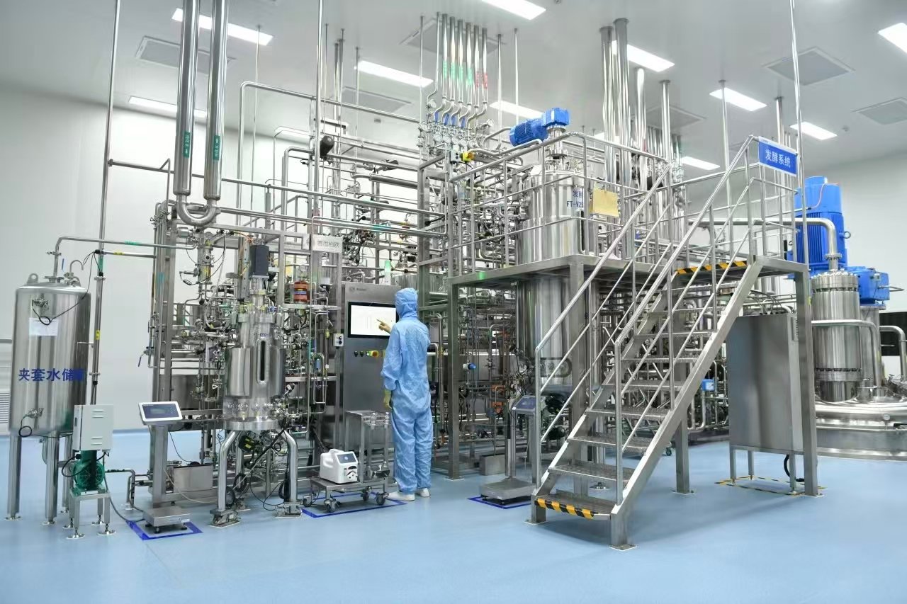
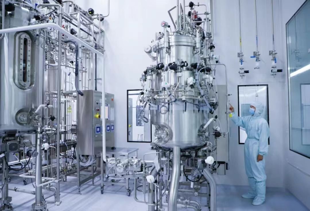
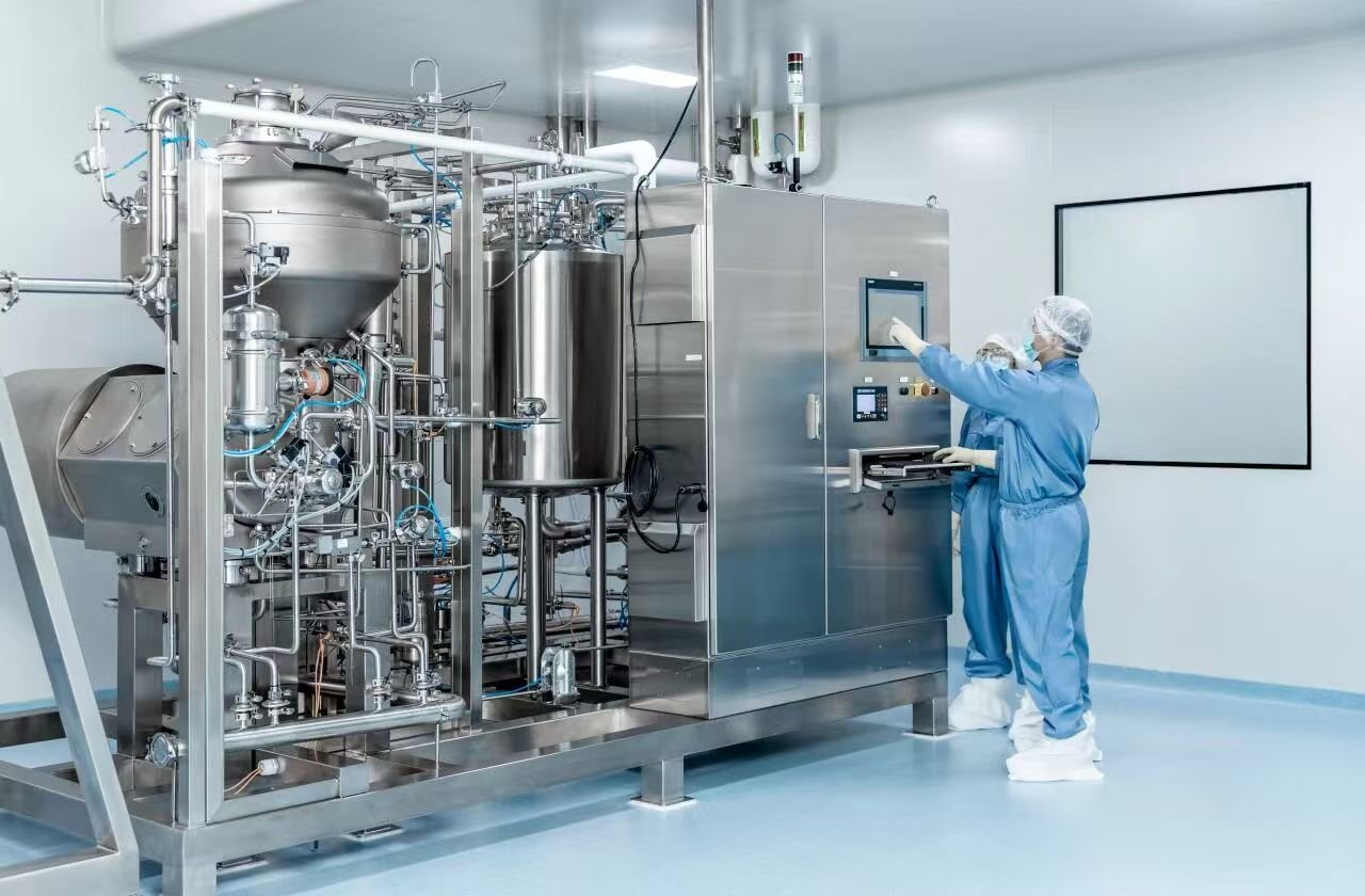

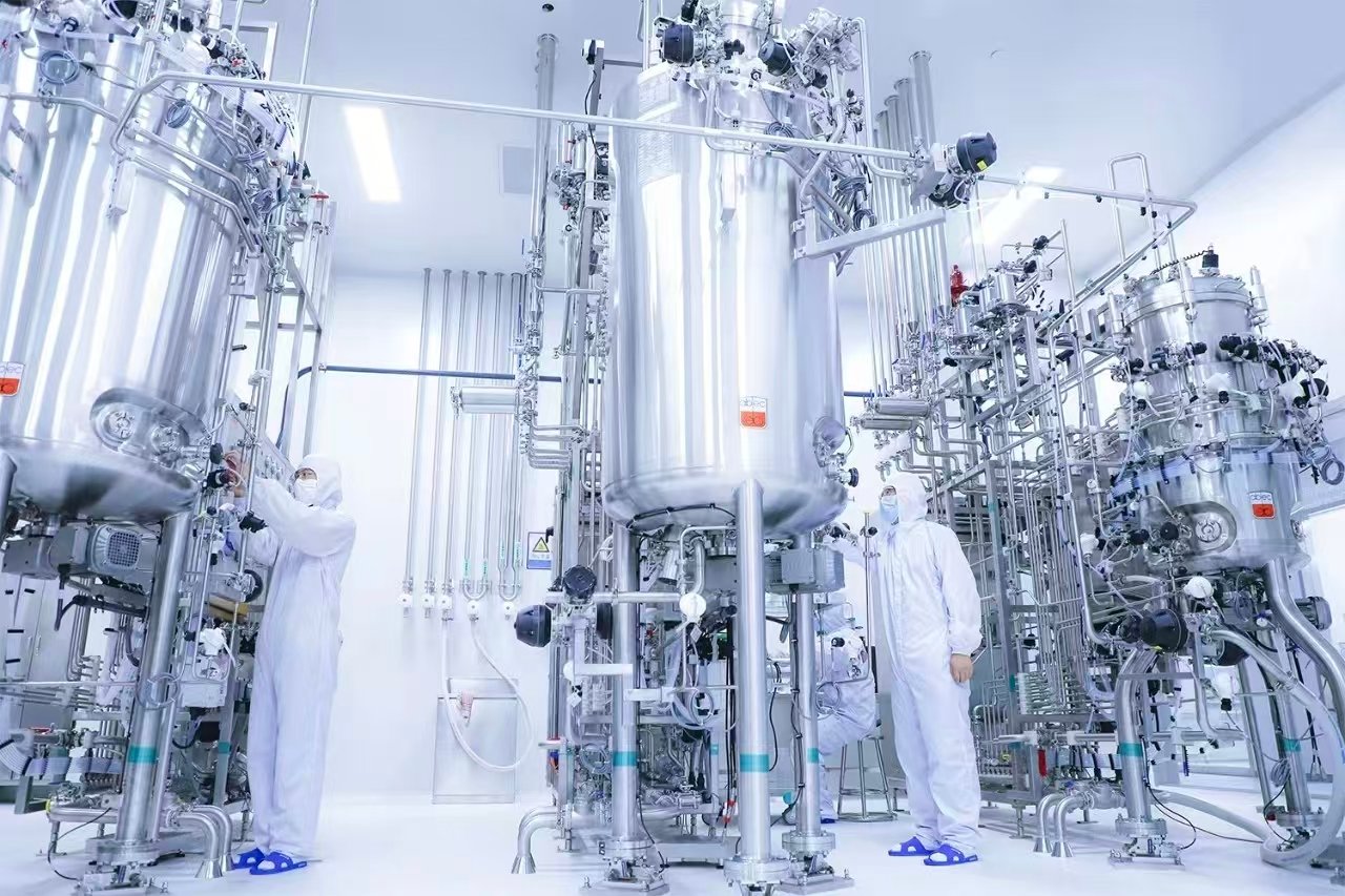
A Piping and Instrumentation Diagram (P&ID) is a normative engineering schematic within the process industries that defines functional interrelationships among process equipment, piping networks, field instrumentation and control components. It captures authoritative technical information including equipment tag identifiers, piping specifications, valve classification, instrument loop tagging, control philosophies and system demarcation boundaries. As a primary design deliverable, it underpins the entire plant engineering workflow.
Within fermentation engineering, the P&ID fulfills three fundamental technical roles:
1. As a foundational design‑phase document, it establishes the technical baseline for equipment specification, piping routing and control‑system engineering.
2. It serves as the authoritative execution reference for fabrication and site erection, ensuring physical implementation conforms to approved design intent.
3. It constitutes controlled technical documentation for operation‑maintenance activities, supporting process performance optimization, root‑cause anomaly investigation and formal engineering change management.
Employing ISO‑standardized graphical symbols and traceable annotations, the P&ID fully documents subsystem interconnections, closed‑loop control strategies and safety interlock logic for fermenter units. It represents a critical technical artifact for evaluating fermenter system architecture and dynamic operational behavior.
Interpreting Seven Core Fermenter Sub‑Systems from P&ID Drawings
01 Air Supply System (Sparger Circuit)
Oxygen acts as an essential metabolic substrate for aerobic microbial cultures. On the P&ID, the air supply circuit typically originates at the gas feed inlet, traverses sterile filtration assemblies and mass‑flow control devices, and terminates at the annular sparger installed at the fermenter bottom. This circuit is differentiated by dedicated line notation, with pressure, volumetric flow and temperature measurement points explicitly annotated.
The P&ID enables unambiguous visualization of the aeration‑system control hierarchy. Mass flow controllers modulate inlet aeration throughput, while dissolved‑oxygen (DO) transmitters acquire real‑time oxygen‑concentration readings from fermentation broth. The automation system manipulates agitator rotational speed and aeration rate against validated process setpoints to realize closed‑loop feedback regulation.
Upon microbial transition into the exponential growth phase, elevated oxygen‑uptake rates trigger automatic aeration ramp‑up, sustaining dissolved‑oxygen levels within predefined operating envelopes. Valve and instrument tag numbers embedded within the P&ID provide traceable references for automation commissioning, loop tuning and in‑service anomaly diagnostics.
02 Feed System (Feed Circuit)
Feed circuits deliver sterile nutrient streams, encompassing carbon sources, nitrogen sources and inorganic salt formulations, into the bioreactor vessel. On the P&ID, feed lines run from nutrient preparation vessels via peristaltic metering pumps and sterile filter assemblies to either the top head nozzle or side‑wall process port of the fermenter. Locations of flow‑measurement instrumentation, gravimetric weighing modules and anti‑reflux protection assemblies are formally marked.
Feed‑system design exerts direct influence over fermentation stability and target‑product titer performance. The P&ID defines piping topology, valve arrangement philosophy and hygienic connection schemes to enforce feeding controllability and process containment integrity. Load‑cell arrays or gravimetric weighing stations facilitate feed‑mass metering and material‑balance computation; metrological attributes including accuracy class, measuring range and dynamic response are specified via instrument tagging and associated technical datasheet cross‑references.
Furthermore, P&ID cross‑reference notations between feed circuits and pH / DO regulatory loops illustrate interlocked control logic that synchronizes feeding profiles with critical process‑parameter trajectories.
03 Steam‑in‑Place (SIP) System
Steam‑in‑Place (SIP) constitutes the engineering foundation for fermenter aseptic operation. On the P&ID, pure‑steam distribution piping connects clean‑steam generation sources through steam‑trap manifolds and temperature‑pressure measurement taps to sterilization ports on process vessels and associated piping networks. Steam circuits are graphically distinguished, with qualified sterilization temperature, pressure and thermal‑hold duration parameters documented.
The P&ID delineates the complete physical scope of SIP coverage: process vessels, piping runs, sampling valves, sensor nozzle ports and exhaust‑gas sterile filters. Sequential SIP cycle logic — heat‑up, thermal hold, pressure retention and controlled cool‑down — is represented as formalized control loops. Post‑sterilisation automatic pressure preservation mitigates retrograde non‑sterile air ingress and maintains aseptic boundary integrity. Steam‑trap staging and condensate‑drain layout depicted on the P&ID reflect established engineering practice for condensate evacuation and thermal‑energy utilization efficiency.
04 Temperature Control System
Microbial metabolic activity exhibits pronounced thermal sensitivity; thermal regulation is realized via vessel jacket structures or internal heat‑exchange coils. On the P&ID, chilled‑water service circuits and steam heating circuits interface with jacket inlet and outlet nozzles to establish closed‑loop thermal‑control loops. Tag identifiers and placement coordinates for PT100 RTD sensors, heat‑exchange equipment, circulation pumps and modulating control valves are specified.
For large‑scale production‑grade fermenters, the P&ID may document multi‑zoned thermal‑control architecture, whereby the vessel is compartmentalized into independently regulated upper, middle and lower thermal segments. Zone‑wise chilled‑water flow modulation constrains axial temperature gradients within qualified acceptance limits. PID tuning logic for thermal‑control loops is denoted by standard automation symbols, delivering definitive guidance for DCS/PLC commissioning. Alternative jacket construction concepts — full‑volume jacket, half‑pipe coil jacket and honeycomb‑type jacket — are represented by differentiated annotation conventions, embodying well‑recognized engineering trade‑offs between heat‑transfer performance and hygienic cleanability.
05 Exhaust System
Gaseous metabolic by‑products, predominantly carbon dioxide, require controlled, safely contained discharge with environmental mitigation provisions. On the P&ID, exhaust piping originates at the fermenter top head, passes through vapor condensers and sterile barrier filters prior to feeding into off‑gas abatement units. Pressure sensing taps, flow‑monitoring points and off‑gas analytical take‑off ports are annotated.
Exhaust‑system design must reconcile vessel pressure stabilization and aseptic containment requirements. Fermenters routinely operate under slight positive gauge pressure; hydraulic resistance across the exhaust train directly governs vessel‑pressure dynamic stability. The P&ID captures full exhaust‑train configuration, including condensers to suppress broth aerosol entrainment and sterile filters to block upstream ingress of environmental contaminants.
Instrument take‑off annotations for off‑gas analytical hardware establish the piping infrastructure required for oxygen‑uptake rate (OUR) and carbon‑dioxide evolution rate (CER) determination, supporting metabolic‑flux analysis workflows.
06 Sampling System
Sampling circuits extract representative fermentation‑broth aliquots to enable monitoring of cell growth kinetics, pH, product concentration and other critical quality attributes (CQAs). On the P&ID, sampling lines branch from vessel side‑wall nozzles and route through steam‑barrier valve assemblies and steam traps towards sampling access points. Valve tag identifiers, steam‑barrier configuration and sampling‑sequence control logic are formally documented.
Sampling hardware design shall satisfy three core criteria: sample representativeness, aseptic integrity and operational safety. The P&ID imposes constraints on sampling‑line dead‑volume, defines flushing protocols and marks steam‑sterilization interfaces. These design attributes prevent adventitious contamination during sampling operations while minimizing net volume depletion from the bioreactor. Steam‑barrier valves and steam‑trap assemblies follow ISA‑standard symbol conventions, explicitly communicating design intent for sampling‑port sterilization and cross‑contamination risk mitigation.
07 Sensor and Control System
Modern fermenter platforms are equipped with field transmitters for pH, dissolved‑oxygen (DO), temperature, foam level and vessel pressure. On the P&ID, field instruments are rendered per ISA‑5.1 symbol standards, interconnected via signal cabling to PLC or DCS process‑control platforms. Instrument tag numbers, calibrated measurement ranges, accuracy classes and mounting orientation requirements are annotated.
Sensor nozzle connections adhere to hygienic‑design principles, mandating flanged interfaces compliant with 3‑A or EHEDG specifications, with contact‑surface roughness Ra ≤ 0.8 μm.
The P&ID illustrates sensor‑to‑vessel interface geometry incorporating integrated steam‑barrier features. During SIP cycles, live clean steam is applied to form a continuous aseptic barrier, prohibiting ingress of ambient air and exogenous microbial contaminants. At the automation layer, control‑loop symbols trace complete signal pathways: from field‑installed sensing elements through controller logic to final actuating elements, with explicit notation for setpoints, process variables and controller output signals.
Engineering Value of P&ID in Fermenter Capital‑Project Design
01 System Integration and Scope‑Boundary Demarcation
The P&ID formalizes physical and functional system boundaries for fermenter installations, clearly segregating vendor‑supplied scope and customer‑furnished utilities, including chilled‑water distribution, CIP media circuits and instrument‑air supply networks.
Project engineers derive subsystem‑to‑subsystem interface requirements from P&ID documentation, aligning deliverables across design, procurement, fabrication and qualification lifecycles. Rigorous boundary definition provides the technical foundation for work‑package partitioning and contractual responsibility assignment.
02 Control‑Philosophy Visualization
The P&ID graphically articulates the fermenter control philosophy. Each functional control loop consists of primary measuring elements (field transmitters), process‑controller hardware (PLC/DCS) and final actuating elements (modulating valves, metering pumps, agitator drive units). Signal propagation paths are represented by dashed‑line notation and dedicated automation symbols. This unified graphical formalism enables seamless cross‑disciplinary collaboration among process engineers, automation specialists and operations‑maintenance personnel.
03 Safety Interlock Implementation and Regulatory Compliance
The P&ID documents Safety Instrumented System (SIS) hardware arrangements, including emergency‑shutdown sequences, over‑pressure protection, high‑low temperature alarm interlocks and low‑level protective trips. Within GMP / cGMP and ISA‑S88 regulatory frameworks, the P&ID constitutes a mandatory component of the qualification documentation suite. It furnishes objective evidence that fermenter design satisfies regulatory expectations for aseptic processing, closed‑loop process control and electronic‑data integrity. P&ID version control and formal change‑control workflows represent core elements of the site quality‑management system (QMS).
04 Operational‑Maintenance Enablement and Root‑Cause Analysis
Throughout the asset operational lifecycle, the P&ID functions as the primary controlled reference document for maintenance teams to map system topology, execute fault‑isolation procedures and perform planned maintenance activities. Field‑located instruments, valve assemblies and piping segments can be rapidly correlated against schematic drawings to interpret system responses to process deviations. Upon occurrence of process excursions such as DO drift, thermal oscillation or pressure alarm events, operational personnel trace relevant control loops against the P&ID to isolate potential root‑cause candidates.
Summary
The P&ID is a core controlled engineering deliverable for fermenter design; its practical value extends substantially beyond static schematic representation. It enables holistic comprehension of design principles and functional interplay across seven key fermenter subsystems: air supply, nutrient feeding, SIP sterilization, thermal regulation, exhaust‑gas handling, aseptic sampling and sensor‑driven process control. Every piping segment, valve assembly and instrument symbol within the P&ID maps directly to defined fermentation‑process requirements and their physical engineering realization.
Bioprocess R&D and engineering practitioners should avoid limiting their analytical scope exclusively to shake‑flask and laboratory‑scale bioreactor experimental datasets. Competent P&ID literacy is indispensable: it allows stakeholders to decode microbial performance requirements embedded within each circuit and grasp multidimensional coupling effects among hardware design, bioprocess kinetics and automated process control. Ranging from conceptual‑design reviews and manufacturing quality assurance through production‑stage process optimization, the P&ID accompanies the full asset lifecycle, furnishing traceable controlled technical records for design, qualification, operation and maintenance. Proficiency in P&ID interpretation underpins robust understanding of fermenter design fundamentals and integrated system‑level performance.