


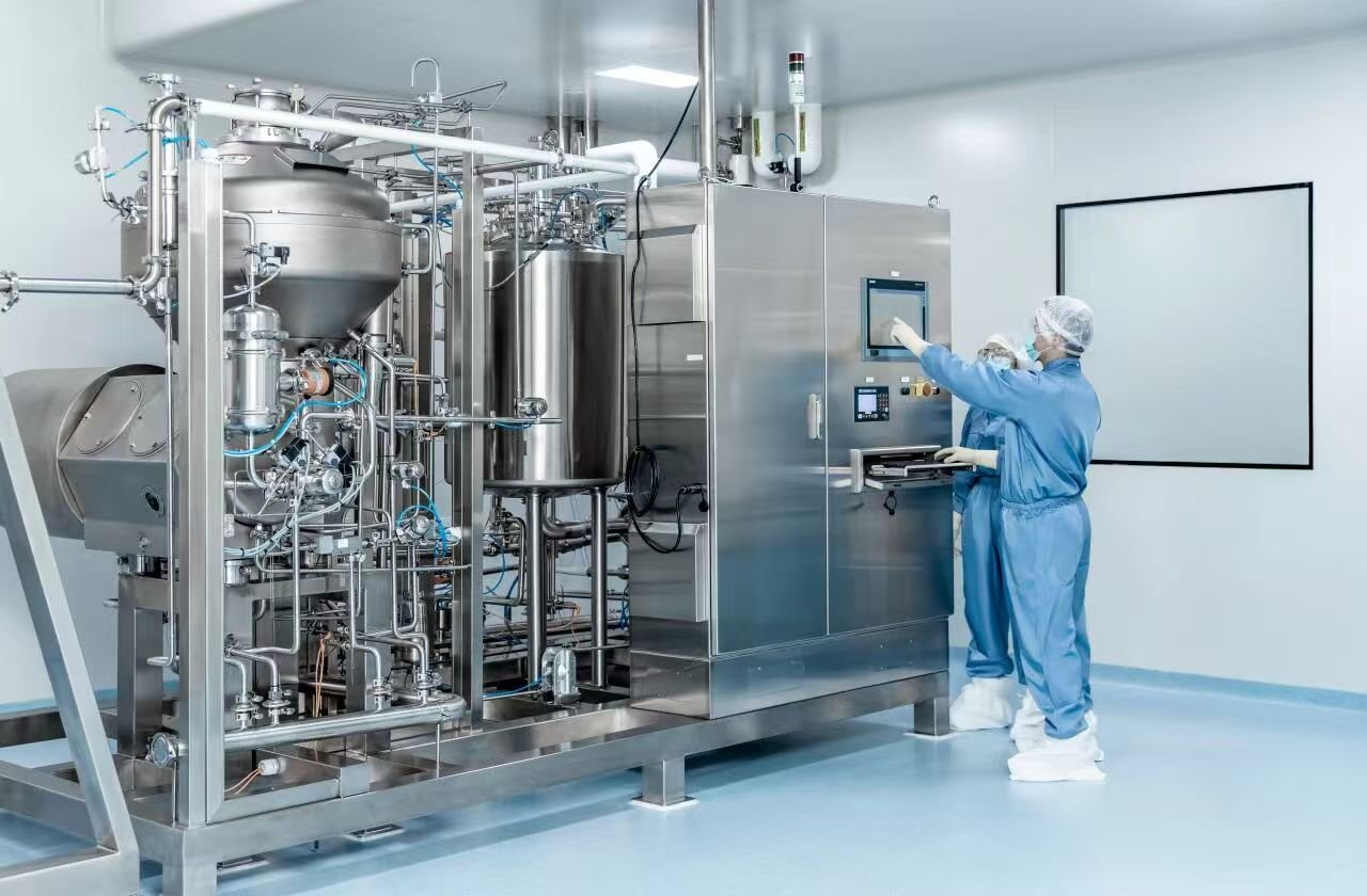
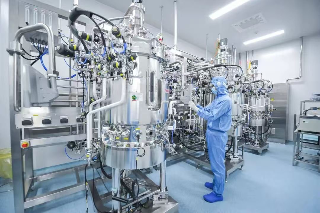
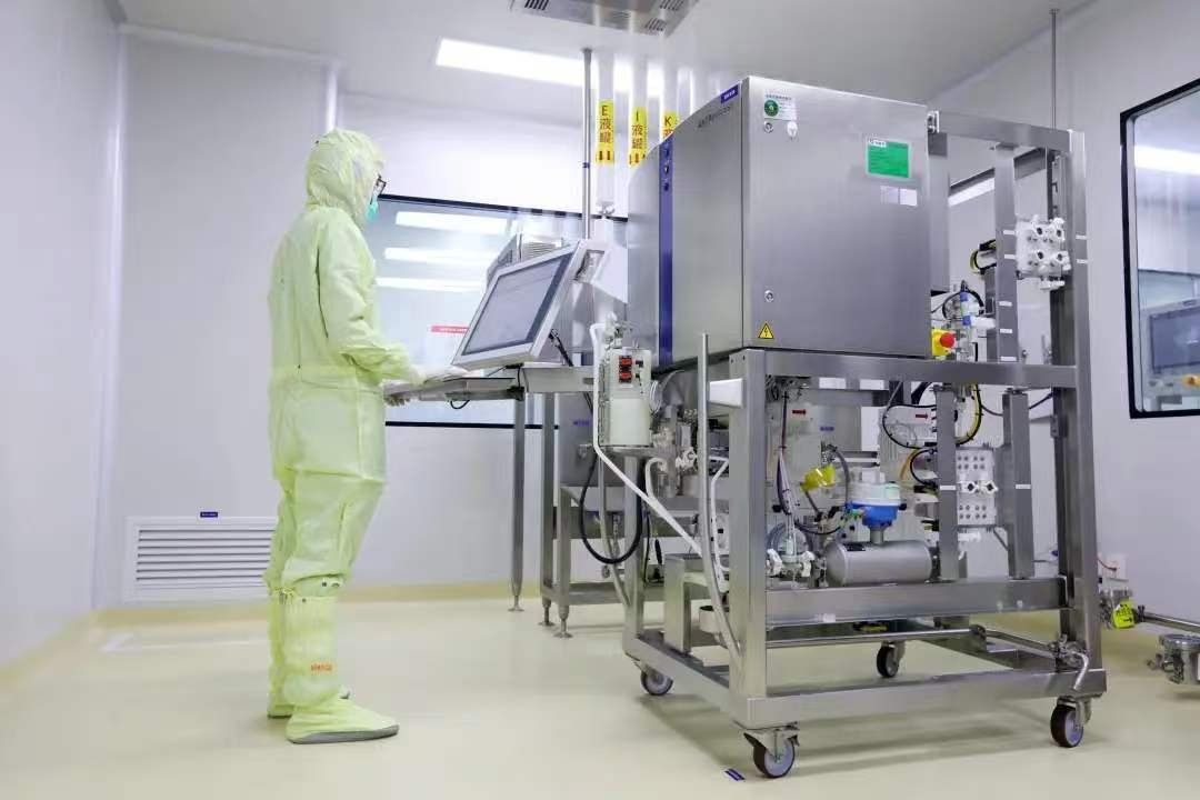
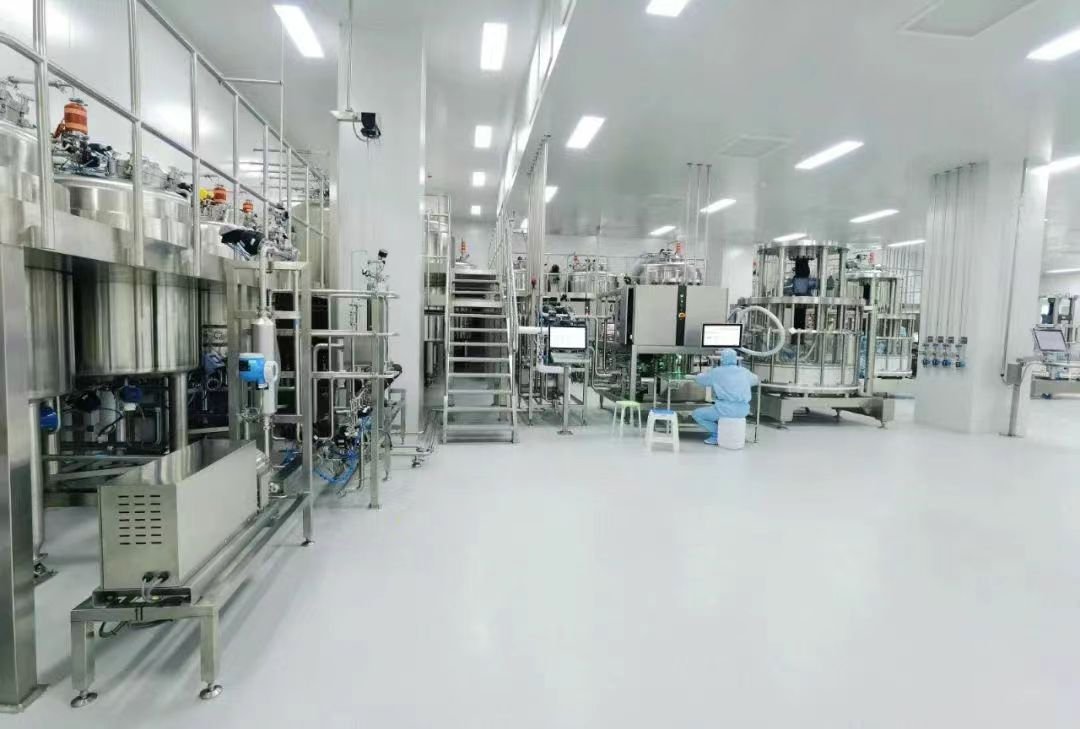
Biopharmaceutical clean rooms typically house processes and equipment requiring utilities such as water, electricity, and compressed air. The sources of these utilities are usually located outside the clean room. During the design phase, a utility matrix is developed in conjunction with the end users and equipment manufacturers, identifying all equipment and utilities needed. This is the basis for determining the capacity of the utility systems as well as the point of use location of specific utilities.
Clean Utilities
Clean utilities are typically those utilities required by the production process that have a direct impact on the quality of the product. In this way, the cleanliness of these utilities needs to be as pure, if not more so, than the product being produced to ensure that no new contaminant is introduced into the production process. For biopharmaceutical production, these utilities generally comprise:
● Water for Injection (WFI) and purified water (PW)
● Clean steam
● Clean compressed air
● Clean process gases (O2, N2, CO2, etc.)
WFI and PW are utilized for makeup of buffers and cell culture media, both of which come into direct contact with the product. Furthermore, PW and WFI are also utilised for CIP operations as discussed previously. Clean steam is utilised as a medium for sterilization of product contacting surfaces (where needed). Clean compressed air is used for blow down of transfer pipes and drying of product contacting surfaces after cleaning and sterilizing. It is also utilised in pneumatic valves within the transfer pipe network and unit operations. Clean process gases are utilized extensively within the cell culture processes.
Technical (black) Utilities
Technical utilities (sometimes referred to as black utilities) are those utilities that directly support the process operation but do not have any direct contact with the product. Technical utilities are generally site or building systems that are either used as inputs for clean utility generation (e.g., potable water) or are utilized in support of the manufacturing process (e.g., chilled water/steam to heat/cool jacketed vessels). Technical utilities may be comprised, but are not limited to, the following for a biopharmaceutical facility:
● Potable water—as an input to higher grades of water use and for use within the domestic systems of a facility (e.g., bathrooms, and kitchens/canteens)
● Fire water—a safety reservoir for fire services or sprinkler systems
● Cooling/chilled water/glycol—a utility used for non-product contacting cooling applications via heat exchanger or jacket
● Hot water/technical steam—a utility required for non-product contacting heating applications
● Electrical power
● Natural or liquefied gas—utility needed for firing gas boilers required for the generation of technical steam
● Waste water collection/inactivation (see Section 45.7.6)
The following sections discuss the major utility system needs that should be considered in the design of a biopharmaceutical facility.
Water
The water used in biopharmaceutical manufacturing must be appropriate for the process step. The degree of acceptance is determined by the level of cleanliness required by each step. Differing grades of water or water for compendial use (that is, water complying with the pharmacopeia guidelines) depend on the regional guidelines. Purity is based on conductivity, pH, total organic carbon (TOC), and endotoxin content. The higher the grade of water required, the more stringent the requirement. No specific guidance is given as to what grade of water should be used where, and thus it is established by the manufacturer [41]. Therefore, for the specification of each water grade, the designer should refer to the United States pharmacopeia (USP), WHO, or European pharmacopoeia (EUPH) or other region-specific guidelines to ensure an informed decision about the appropriate grade of water being used for a specific process step.
Although nomenclature differs on a regional basis, the U.S. Pharmacopeia lists grades as USP purified water (PW) and high purified water (HPW), among others, the highest grade of water typically utilized within a biopharmaceutical facility is that of water for injection (WFI). WFI is generally utilized for all product contacting solutions such as buffers and cell culture media. Though in some instances, PW may be used for cell culture media make up, since its use would be at a stage of the process where the product is in a less pure form. As discussed previously, clean-in-place operations typically use PW and WFI within the different phases of the cleaning cycle.
The various grades of water found in pharmaceutical and biotech facilities are typically generated in a continuous water treatment system. The starting point is usually potable water that is fed to the site from a municipal water supply. It is a GMP requirement by all the major international authorities to use drinkable water of at least WHO-quality as raw water for the generation of pharmaceutical water quality. The specific analysis data must be checked for the design of the water treatment system.
As a first step, the potable water is filtered to remove any particulates that are carried by the water into the facility. A softener bed is used to remove substances such as calcium and magnesium (cations) from the water to minimize scale deposits in the plant utility systems, and more importantly, the water purification filters and distillation units. Before softened water can be further purified, it is passed through an activated carbon filter to remove oxidizing substances (e.g., chlorine and its compounds) and low molecular-weight organic materials before it is finally purified by reverse osmosis and/or distillation.
If purified water (PW) or USP purified water, or highly purified water is the compendial process water, an RO filter system with an electro-deionisation (EDI) step is the most common way to meet the requirements for conductivity, pH, total organic carbon (TOC), and bioburden. These grades of water are generated and distributed around the facility at ambient temperature through a recirculating loop with specific tap points located as needed within the facility.
For WFI generation, three different approaches can be undertaken for generation:
i) Distillation—either via vapor compression or multi-effect
ii) Reverse osmosis (RO) iii) Ultrafiltration
Multi-effect distillation is achieved by distillation columns that perform both an evaporation and condensing process. Treated water is evaporated by technical (or plant) steam, as a heating source and subsequently condensed in a series of distillation columns and heat exchangers for energy- saving reasons. The number of columns is chosen to be sufficient to obtain production of WFI without need for external cooling. The WFI is produced at a minimum temperature of 80°C.
Vapor compression distillation is a method of evaporation in which a process fluid is boiled on one side of the heat transfer surface and the compressed vapor generated is directed to the other side of the heat transfer surface where it is then condensed (giving up its latent heat to the boiling liquid). Heating can be via steam or electricity. Compression is usually accomplished via steam jet ejector or mechanical compressor. The feed water can also be softened water, and as such, PW does not need to be generated for WFI production. Vapor compression stills can produce both hot and cold WFI.
Some facilities are producing WFI or highly purified water by filtration alone in lieu of distillation. The USP allows WFI to be produced by distillation or an equal or superior process [45]. As such, filtration methods such as reverse osmosis (RO) and subsequent ultrafiltration can be utilized for WFI generation if the process adheres to TOC, endotoxin, pH, and conductivity limits. Ultrafiltration (UF) or RO techniques follow the same PW generation process prior to an additional RO or UF step for pyrogen removal, but produce only cold WFI. Currently Europe and China pharmacopeia only allow WFI generation via distillation. However, at the time of this writing, there had already been discussions in Europe about the introduction of ultrafiltration in the near future [49].
Depending on the method used, WFI is generated and distributed around the facility hot (65–80°C), chilled (20–25°C), or at ambient temperature. However, all PW loops are cold loops (20°C). Fig. 45.15 shows that distribution is achieved using a PW/WFI storage tank that is connected to a PW/WFI loop that surrounds the process areas where this quality of water is needed. Tap points are positioned at the point of use within the process suites where WFI or PW is needed. Typically, tap points are needed within the buffer and media preparation suites, the inoculum and other laboratories, and at defined points in the process suites. It should be noted that the connection of WFI/PW loops to any unit operation should be avoided. The risk of contamination due to back pressure causing a reversal of flow from the point of use to the main distribution loop is too high. As such, PW/WFI break tanks are utilized in between the main distribution loop and connected to the unit operation should large volumes of water be needed. If a direct connection is a necessity, for instance, due to space constraints, then appropriate control valves should be employed between the loop and the associated unit to mitigate any risk.
To ensure PW and WFI keep within specifications, microbial growth is minimized by keeping the water flowing at all times via continuously recirculating around the main loop through the distribution tank. Regular sanitization is also advised. Sanitization is achieved through heat or chemical addition (e.g., NaOH or Ozone(O3)/H2O2 dosing). In some cases, a UV system may also be utilized for disinfection and de-chlorination and to break down the ozone (if used) into O2+H2O.
Sanitization via heating typically takes place overnight, where the PW/WFI loop, which could be cold or ambient during the day, is heated to 80–85°C overnight for a defined period. From this perspective, hot WFI loops have the added advantage (and safety) of being continuously self-sanitizing. Hot WFI loops are a recommendation within the China Pharmacopeia. However, added expense is required as each point of use tap, where WFI can be drawn from the distribution loop, will require a heat exchanger to cool the water should lower temperatures be required. To further prevent the possibility of microbial growth, periodic steam sanitization of open tap points is recommended before and after use, to prevent contamination when the distribution loop is exposed to the facility environment. Periodic steam sanitization of the distribution loop is also recommended, requiring a clean steam distribution loop to be run in parallel to the WFI distribution loop throughout the facility.
The materials of construction used for WFI/PW loops and tanks are of great importance in ensuring minimization of microbial growth. High grade stainless steel such as 316 or 316L should be used with polished surfaces (Ra<0.5μm) to ensure no ridges or crevasses exist that could stagnate water. As such, WFI/PW storage tank and distribution loops are highly costly and contribute a significant portion to the overall CAPEX of the facility.
Overly conservative use of WFI for all uses may result in a more expensive system, higher operating costs, and QC monitoring costs. However, in smaller facilities there is a trade-off where the greater operational cost of WFI is traded for a single distribution loop for the facility rather than an additional loop for PW. For instance, in the case of a predominantly single-use facility, where CIP can essentially be eliminated, there is less of a need for a PW loop within the facility as nearly all water needed would be for direct process needs. As such, the savings in CAPEX for elimination of PW generation and distribution could be significant.
Steam
In general, two types of steam are used within the biopharmaceutical facility:
1) Technical or black steam produced from a boiler. Technical steam is produced, in most cases, using conventional fire-tube steam boilers whose typical design and construction are well known.
Such boilers are almost always provided with systems that inject additives in the feed water to protect the boiler and steam distribution piping from scale and corrosion. Some of these scale and corrosion inhibitors may, and often do, include amines and other substances that may not be acceptable in steam being used in biopharmaceutical processes. The designer must determine what additives are used, and verify if they are acceptable in the application (i.e., not to add any impurities or create a reaction in the drug product). Utility steam can be filtered to remove particulate matter, but filtration does not remove dissolved substances and volatiles such as amines.
The main use of technical steam is for heating of non-product contacting surfaces and systems. Applications could include the heat source for jacketed vessels or heat exchangers around the facility.
2) Clean steam—steam not produced from a boiler. Clean steam is generated from treated water free of volatile additives, such as amines or hydrazines, and is used for thermal disinfection or sterilization processes. It is considered especially important to preclude such contamination from injectable drug products. No chemical additions are made to clean steam, which in most cases should be particulate-free and indeed free of any contamination.
The main use of clean steam within a biopharmaceutical facility is for sterilization of products, and more typically, equipment. Typically, in these processes, clean steam is injected into equipment or piping to create a sterile environment, or into autoclaves. Sometimes it may even be used within the HVAC system for clean room humidification. When steam is used for indirect humidification, such as injection into HVAC air streams prior to final air filtration, the steam does not need to be purer than the air with which it is being mixed. However, when humidifying process areas, the potential level of impurities should be evaluated to ascertain the impact on the final drug product. This is particularly important in areas where open processing takes place, such as aseptic filling suites and formulation areas. If the diluted water vapor is found to contribute significantly to the contamination of the drug, a purer grade of steam should be selected.
In contrast to water, there is no pharmacopoeia standard for clean steam (or any type of steam for use in pharmaceutical manufacturing). A specification for the purity of such steam must be prepared by each manufacturer and the specification must be such that they meet the cGMP requirement to avoid contamination of the product. The exception being European regulators, who have defined specific criteria for pharmaceutical steam used for equipment sterilization (European Standard EN 285—Steam Sterilizers—reference section 13.3). These cover acceptable levels of saturation or dryness, the level of superheat, and the volume of non-condensable gases present. In theory, there could be a wide range of different clean steam specifications applicable to products of different degrees of purity and different stages of manufacture. In practise, the pharmaceutical industry has tended to consolidate around specifications where the steam condensate meets the pharmacopeia specifications for PW and WFI.
Conservatively, manufacturers tend to produce clean steam quality to a standard whereby the condensate produced meets WFI requirements for conductivity, TOC, and endotoxin (the microbial limits is usually excluded as it is acknowledged that viable microorganisms cannot survive in steam systems).
Clean steam (CS) is produced in specially designed non-fired generators or from the first effect of multi-effect WFI stills, which do not use scale or corrosion inhibitor additives. The generator is fed with water pre-treated for removing elements that contribute to scaling or corrosion, and the materials of construction are resistant to corrosion by steam that has no corrosion inhibitors. The dedicated CS generator is very similar in design and construction to the first effect of a multi-effect distillation still. From this perspective, in some cases where the CS utilization of the facility is low (e.g., within a predominantly single-use facility), multi-effect distillation may be shared between clean steam and WFI generation, thus saving associated cost, space, installation, operation, and maintenance requirements.
As with the water systems, the CS generator feeds a distribution line that runs around the facility and usually follows that of the WFI loop—for ease of sanitization. User points are defined during the process design phase and are usually associated with unit operations that require SIP (e.g., stainless steel bioreactors) or CS as a utility for their use (e.g., autoclave or HVAC humidification).
Distribution systems for clean steam follow the same good engineering practices commonly used for utility steam, with the exception that contact materials must be inert to the aggressive nature of clean steam. Corrosion-resistant 304, 316, or 316L grade stainless steel “tubing” or solid-drawn “pipe” are commonly used. Surface finish is not critical due to the self-sanitizing nature of the clean steam. Piping must be designed to allow for thermal expansion and to drain condensate. Sanitary clamps or pipe flanges are most commonly used where the piping must be broken, but welded connections are used as much as possible to eliminate maintenance costs and potential for leaks. Threaded connections may be suitable for instrumentation if positioned to drain condensate and remain hot. Steam quality sampling may be determined during “commissioning” and consistency ensured based on the proper location and subsequent maintenance of traps, entrainment separators, and vents. When required by the process, the steam purity shall be monitored through acceptable sampling techniques. A slipstream of the steam may be passed through a sample condenser/cooler, and fitted with a sampling valve. Sample coolers can be fitted to the CS generator, or located in the distribution line, or at the use point (recommended location), or a combination thereof. It is common practice to fit sample coolers with conductivity monitors and alarms.
Process Gases
Process gases are defined as gases that can affect product quality. Generally, in biopharmaceutical processing the following clean process gases are utilized in manufacturing:
● Nitrogen (N2)
● Oxygen (O2)
● Argon (Ar)
● Carbon dioxide (CO2)
● Compressed air (CA)
Oxygen, carbon dioxide, and compressed air are often used in the cultivation of cells within a bioreactor or fermenter (see Chapters 5 and 31). CO2 may also be used in incubator systems used for initial cell growth. N2 is most commonly used as an inert gas for the conditioning of products in storage and transportation. Normal atmosphere is sometimes not allowed to contact the product either in process or in the final package. This is done if oxygen might promote the growth of undesired organisms or cause oxidation of the product. Normal air may be replaced in tanks and/or containers with inert process gases—possibly nitrogen, argon, or carbon dioxide. Tanks are filled with the gas as liquid is removed and the gas is allowed to escape when the tanks are filled. During final packaging, as containers are filled, a process gas ‘blanket’ may be injected into the container to displace air before container closure. In specific applications, argon or carbon dioxide may be used instead of nitrogen. Blanketing with an inert gas, such as nitrogen, is commonly used, primarily to minimize the risk of fire, dust explosions, and other explosions [50].
Nitrogen, argon, and carbon dioxide are also used during the manufacture of bulk drug substances (BDSs) (e.g., for drying operations) and in the production of finished goods. Compressed air is used throughout the production facility within pneumatic systems (e.g., or valve control).
Storage and Distribution
Process gases are typically supplied to the production facility by gas suppliers and are stored on site within liquid storage vessels, transportable liquid containers, or high pressure gas cylinders with manifolds. These are generally located outside the facility with supply piping connecting it to the necessary operations within.
Most user applications use gases in their gaseous state. Supplied liquid gas is therefore converted to a gas using a vaporizing system. The vaporizing system may utilize heat from ambient air, hot water, or steam. Vaporizing systems are usually equipped with a protective device downstream to prevent cryogenic liquid from reaching the facility supply line or process, which may not be designed to withstand the exposure to cryogenic temperature. It would be the responsibility of the gas suppliers to maintain the supply of gases to the facility, whether through top-up of storage vessels via tanker or replacement of cylinders. The facility designers therefore should estimate the quantity of gas supply necessary to ensure that manufacturing operations are interrupted before selecting the best method of gas storage on site.
In some cases, where large volumes of gases are constantly required, or if the facility is in a remote area, gases may be extracted from the atmosphere through an air separation plant (achieved through fractional distillation of liquefied air). In this case, the air separation plant would become part of the overall facility design and be the responsibility of the facility owners. Supply and quality can be controlled to internal specifications more easily; however, the cost associated with building such an ancillary operation would need to be weighed against the advantages. It may be more frugal, for instance, to consider generation of compressed air on site. CA systems are, in their most simplistic form, generally comprised of a compressor with a filtration system and a dryer. The drying of air is important to reduce moisture content that will help to prevent the chances of microbiological contamination.
Atmospheric air that is fed to a compressor is usually discharged at pressure and will usually be saturated and contain particulates (usually with a particle size of less than 10μm, ie, at sizes below the typical size limit of an inlet air filter). If the compressor is a lubricated compressor, the discharge air can also contain oil as a vapor or particulate that could lead to a contamination risk. Typically, oil content in the discharge of a lubricated compressor is around 3 ppm. Oil removal filters should be included in the sequence if lubricated compressors are used.
Process Gases and GMP
Gases themselves are not medicinal products and as such do not have to be produced following cGMP. However, many regulatory bodies do have regulations relating to the use of process gases. The ICH Q7 considers gases as “process aids” to be used to aid in the manufacture of intermediates or active pharmaceutical ingredients. Similarly, the U.S. FDA considers process gases as “components” intended for use in the manufacture of a drug product.
Therefore, gases should be purchased according to an agreed-upon specification and delivered with a Certificate of Conformity (CoC) or a Certificate of Analysis (CoA), depending on the criticality of the gas (i.e., where in the process the gas is to be used).
Gas distribution systems are usually protected with filters rated at 1μm or smaller at the generation source. Where sterile gas or sterile venting is required, this is usually provided by a 0.2μm-rated hydrophobic sterilizing grade filter at the points of delivery or use. Sterile gas/vent filters can either be pre-sterilized by autoclaving and aseptically installed, or sterilized in situ by steaming in place (SIP). For single-use bioreactors and other disposable systems, filters can be sterilized using gamma irradiation. Some 0.2μm-rated membrane filters are also rated for removal of airborne viruses down to 20 nm (0.020μm) and airborne particles as fine as 0.003μm. This is possible because filters are typically rated for particle/microbial size removal from liquids, whereas additional removal mechanisms occur in gases that enhance removal of particles finer than the liquid pore size rating. Filters should be integrity tested before use, usually via either bubble point pressure test, flow forward (diffusion) test, or water intrusion test.
Process gas filters are also critical to the quality of BDS and biopharmaceutical production. These hydrophobic membrane filters keep particles and bacteria that may be carried by process gas from entering the process. These filters may be used if an inert gas is used for tank ventilation instead of normal air, if the product in the tank is sensitive to oxygen. Another common use of process gas is for ‘modified atmosphere’ packaging—replacing air in bottles or other packages to keep oxygen or other atmospheric gases from the product
Filters used for liquid applications are usually made of materials that attract water—are ‘hydrophilic’—and allow the flow of liquids through the media or membrane with low resistance. For air filtration, it is critical that the media remain dry. If the media becomes wet and the pores are filled with liquid, then the required air flow is restricted and the pressure or vacuum inside the tank can reach critical levels and cause tank failure. The various media used for air filters are ‘hydrophobic’—they repel water—and resist wetting from water vapor.
Filtration of oxygen is a significant safety concern: it leads to accelerated oxidation and corrosion of plastics as well as spontaneous combustion. Because thinner filter components such as non-woven support and drainage layers are much more vulnerable by such oxidation effects, it is recommended to use filters that contain more oxidation resistant materials (e.g., polyamide non-woven layers) instead of the relatively fast degradable and flammable polypropylene non-wovens found in typical air sterilizing polytetrafluoroethylene (PTFE) membrane filters. Beside these degradation effects, oxygen flow builds up static charges on filter media surfaces that can lead to spontaneous discharging with the risk of ignition of degraded organic traces and flammable filter components, followed by combustion and fire generation inside pipes and filter housings. In some locales, such filter installation for gaseous oxygen needs to be approved by special authorities for facility and operator safety.
Based on these facts and the allocated risks, a single-use mode of sterilizing gas filters together with a minimum oxygen concentration for the duration of the fermentation cycle is recommended in addition to general safety guidelines about oxygen handling. Blanketing with an inert gas, such as nitrogen, is commonly used in chemical processes, primarily to minimize the risk of fire, dust explosions, and other explosions. It is also used to prevent undesired reactions with atmospheric oxygen. Blanketing is a method for constantly maintaining a protective layer of gas on top of BDSs. The inert gas replaces humid air or explosive vapor of solvents in the headspace of contained batches. Nitrogen is also used as a blanket in bioreactors for oxygen replacement for anaerobic fermentation processes. On water for injection or purified water, nitrogen blanketing may be used to reduce changes in conductivity associated with dissolved carbon dioxide. Oxygen is commonly used to enrich air and to enhance oxidation. In biological processes, it can also be used to increase the rate of the process (e.g., fermentation) or in the cultivation of mammalian cells.
As a leading process-oriented engineering company, Sino Bioengineering delivers professional bioengineering solutions and comprehensive technical services to clients worldwide.
For more products and solutions: https://sinobioengg.com/category/solution/
For more service: https://sinobioengg.com/category/service/