


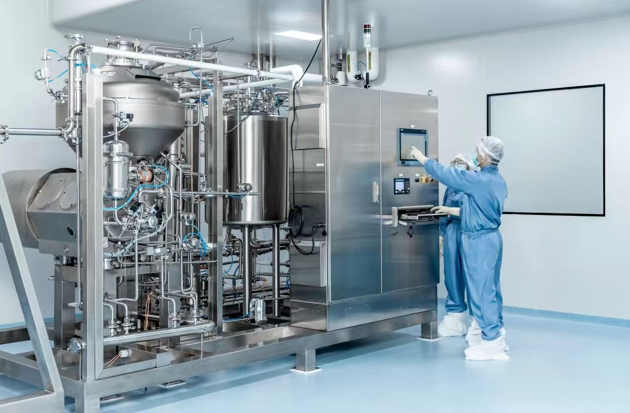
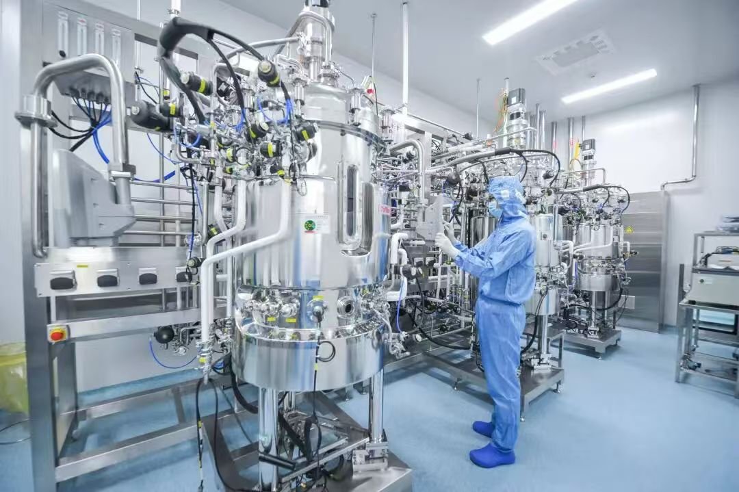
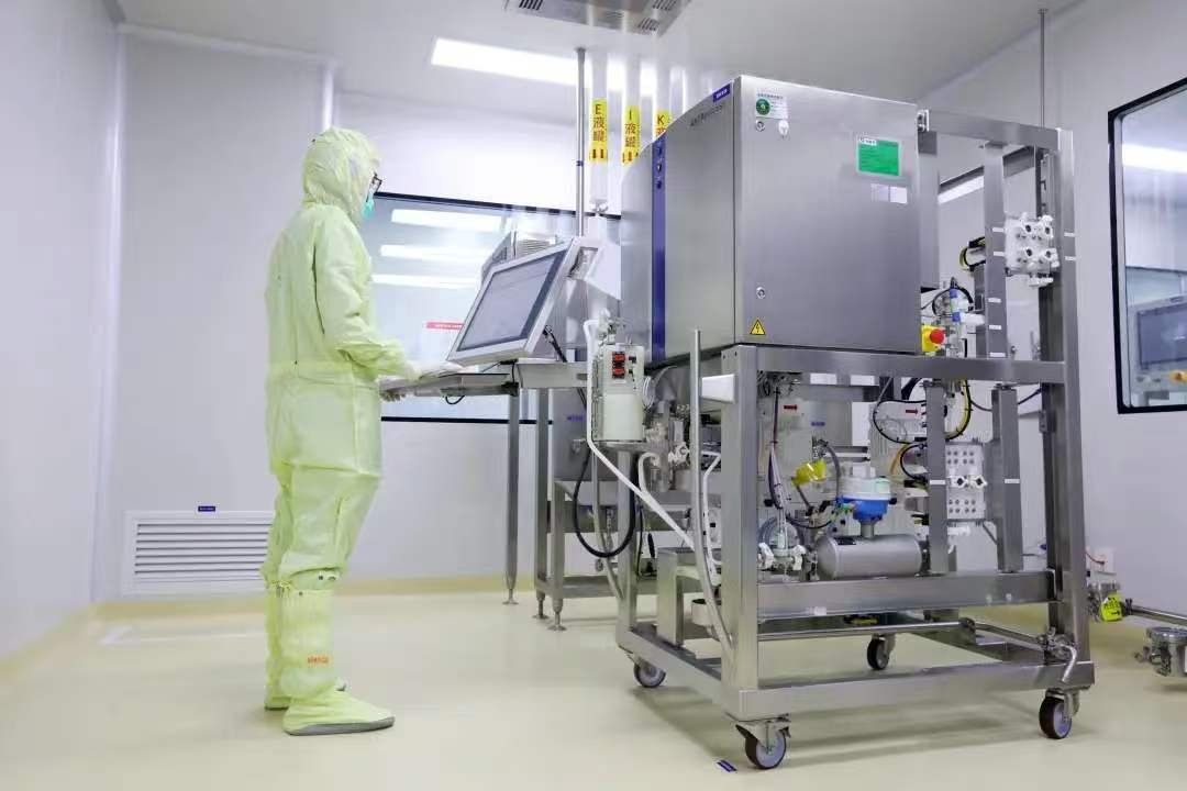
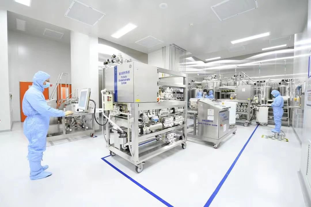
Segregation practices form the fundamental design strategy for the prevention of cross- contamination and protection of quality of the final bulk and intermediate products throughout the manufacturing process.
As a result, segregation is a central paradigm in process and facility design, which ensures product protection in the biopharmaceutical operations. Segregation can be accomplished by:
1. Process design, through system closure
2. Space and environmental controls
3. Procedural and temporal segregation
Segregation by Process Design
The best counter-measure against external contamination of product is to create a manufacturing process that is completely closed to the environment. Closed systems are those that use processing equipment in which the product is protected from contamination in the immediate room environment. An example is the use of closed piping or tubing for solution transfer as opposed to a conduit open to the atmosphere. Closed systems effectively segregate product containing solutions from the room environment by enclosing them fully within a unit operation.
In many closed systems, materials (filtered air, clean steam, water for injection) may enter or leave the system, but the quality of these materials is carefully controlled. In addition, the way these materials are added or removed from the process (e.g., via filtration or aseptic connection), is carefully controlled. Key components of a closed system (such as a bioreactor) should be qualified as appropriate (e.g., pressure decay rates, sterile media holds), to demonstrate that the system can prevent escape of product and entry of contaminants from the external environmental into the product. Operationally, closure in non-aseptic processes may be defined by demonstrating that processes are not affected by the external environment, or that measures are in place to prevent contamination.
The loss of the closed state due to routine or infrequent activities (e.g., maintenance/cleaning) does not negate reliance on closure as a key component of the facility design. In such cases, a validated procedure for re-instituting the closed state should be part of the manufacturing process. These units are termed functionally closed systems . For example, if hoses or aseptic sampling devices are connected to tanks prior to processing, it is acceptable to validate that the CIP and/or SIP systems can properly reduce or maintain bioburden to pre-determined levels and return the system to the previously closed condition. It is the manufacturer’s responsibility to define and validate the sanitization or sterilization process required to return an opened system to a functionally closed system.
An issue currently being debated is related to closed and functionally closed systems and whether these systems can be established with a sufficient degree of confidence so that classified environmental controls (discussed in the next section) around bioprocesses can be reduced or removed. Properly executed risk analysis shows that closed systems can be established and operated with acceptably low probability of contamination. Using closed systems opens up many new possibilities for how facilities are designed and operated and may also present lower risk to the operation and, ultimately, the product.
Many parts of a typical manufacturing process are not completely closed, whether due to technology limitation or via design for ease of operation. Therefore, the product faces certain risks when being exposed to the environment and so in these cases other forms of segregation may be employed. Closed processing is not a full requirement for GMP compliance.
Open systems naturally provide more opportunities for contamination because the process is open to the room environment and handling by operators. There are also safety concerns associated with breaches of product containment. A closed system, by design, provides physical barriers to reduce the risk of contamination and to contain the product. This is important because contamination can be extremely costly, not only in product loss, but also facility shutdowns, cleaning, and validation. Open processing is acceptable where the processing conditions do not expose the process stream to potential risk or where the potential for contamination is minimal. However, the manufacturer should be aware of the impact that such operations can have on the product and provide for appropriate monitoring and relevant testing or process controls as appropriate.
In many cases, locally protected processing, a variation on open processing, is appropriate where local controls can prevent the ingress of environmental contamination into a process stream that is open for a short period of time or for which there is minimal potential for product impact. For locally protected processing, acceptable controls include such applications as HEPA filtered airflow devices and/or gloveboxes/isolators. Where such devices are used, the protection of the product and process step should be demonstrated and documented.
The manufacturing process should be evaluated step by step from raw material to final product in order to determine if each operation can be operated via a closed system or not, as this will have a subsequent impact on the extent of the application of other segregation practices (e.g., environmental controls, spatial segregation, etc.). The determination of whether a system is open or closed should also extend to the how a unit operation is cleaned or dealt with after use. For the purposes of defining the appropriate control strategies and relevant facility requirements, it is necessary to define the relative risks associated with a specific processing step and to clearly define the processing and facility controls that will be implemented to prevent potential negative product impact.
The Impact of Process Technology
The choice of process technology will impact the determination of the extent of system closure. Traditionally in the industry, stainless steel tanks, unit operations, and process piping together with associated instrumentation have been utilized for manufacture. Generally, these technologies in combination with sterile grade filtration or inherent clean in place (CIP) and steam in place (SIP) arrangements have facilitated the classification of these systems as being closed or functionally closed. In some cases, however, due to the mechanical complexity of these components, sufficient cleaning and sanitizing may require the dismantling of these units, which could necessitate exposing product contacting surfaces to the room environment. In such cases, even functional closure could be a state that is difficult to validate. Furthermore, tanks and transfer line systems tend to have the highest odds of sterility failure, and require careful design, installation, and validation. If sterility failures do occur, their causes may be difficult to trace, because both mechanical failure and operator error will need to be considered as the potential causes. For example, performing a pressure leak test of the vessel prior to steaming is a critical part of the SIP protocol. These tests will find most leaks attributable to gaskets or mechanical fittings.
Utilization of single-use technologies (e.g., bioreactors and bags and tubing instead of stainless steel hold tanks and transfer piping) where applicable, is more in line with the concept of closed systems. Product contacting surfaces are typically supplied in a sterile format and they are replaced after use, hence not needing any further repeated manipulation to return to a closed state.
Segregation by Space and Environmental Control
The concept of physically separating the processing of product within a unit operation from the room environment through a closed system can be applied via a more macroscopic approach to whole areas of the facility itself.
Segregation by space and environmental controls, sometimes referred to as “primary level segregation” is the application of physical barriers to define the basic organization of the facility with the aim of minimizing the potential for contamination of the process or cross-contamination of other products. This is usually achieved via walls or other controlled barriers (e.g., airlocks) that aim to establish work areas that separate specific steps in the manufacturing process and create a dedicated built-in path of travel for raw material, product, waste, and personnel as they move through the facility.
Segregation by Space
In biopharmaceutical manufacturing, physical segregation has usually been implemented with a view to minimizing the risk of contamination of an increasingly pure high-value product as it proceeds down the process train. Steps are separated based on the level of inherent risk that their operation or work procedure could cause contamination of a following manufacturing step or work environment. An example of this is the almost universally applied separation between upstream (cell culturing, growth, and harvest) and downstream (product purification) operations. This could also be based on segregation of “live” or “dead” host cell organisms, something which is used considerably in vaccine manufacturing. In many manufacturing facilities, different personnel work with upstream and downstream process operations respectively. Segregation is typically performed to the extent that separate entrances are required to the upstream and downstream production suites. This is so that there is no chance that staff working on upstream activities can enter the downstream purification without having to de-gown and clean themselves first. In this way, contamination of the purification operations with particulates from the upstream can be avoided.
One often underestimated approach in the design of a manufacturing facility is the adherence to viral safety. To comply with regulatory guidelines and in cases where the virus is not the product, it is important to consider where viral clearance takes place in the manufacturing process and which steps provide effective viral inactivation or removal. Well-designed facilities ensure adequate segregation of process intermediates that have been through an effective viral reduction step from those intermediates that have not. Also, dedicated viral clearance must be planned in the manufacturing process to alleviate safety concerns.
Similarly, should a specific, robust viral reduction step be employed as part of a processing scheme then there is usually a segregation of processing operations upstream of the viral reduction step as “pre-viral” and those downstream as “post-viral”. This designation sometimes includes physical segregation of the upstream and downstream processes, including separate processing suites with personnel access and gowning control, segregated HVAC systems, and separate CIP systems, etc. Generally, virus content reduces through the downstream purification steps. Typically for MAb processing, a segregation of the downstream processing area between pre- and post-viral filtration is implemented. This allows for a discrete separation of rooms that house product solutions that may contain viral material and those that can be classed as being virus free.The rationale for this design is to avoid cross-contamination of the post-viral process material with potentially contaminated process material that has not yet been treated for viral reduction.
This type of design approach can become complicated for processes that require more than one defined viral reduction step or when the designer relies on a combination of processing steps for viral clearance.
The segregation concept is applied to situations outside the core manufacturing process as well. For instance, it is typical for there to be a physical separation between raw materials that are derived from animal and non-animal origins. This is again primarily to reduce the potential risk of any animal derived impurities such as viruses from contaminating other materials. Physical segregation is popular from a regulatory point of view as it limits the possibility of human error contributing to contamination risk.
Segregation by Environmental Control—Classified Areas
Biomanufacturing facilities are typically designed using a shell-like control concept, where the most critical process activities are conducted in clean rooms designed to the higher cleanliness standard and surrounded by clean rooms and controlled areas of lower classifications.
The environment within a facility is always controlled to some extent, however, the degree of control is often split into two distinct environmental envelopes; spaces that are deemed controlled-not- classified (CNC), where temperature, pressure, and humidity are generally controlled and monitored, and classified areas within which air cleanliness is additionally controlled and monitored and validated to a specified cleanliness level. Classified areas are referred to as “clean rooms” and cleanliness is defined via a minimum number of airborne particles allowed within the room or within a volume of air.
Outside air acts as a vehicle for bacterial and gaseous contaminants brought in by movement of people, material, and via the air supply to the building. Since many of these airborne contaminants are harmful to products (and potentially people), their removal is necessary to satisfy cGMP requirements for product purity and control. Removal is performed by means of air filtration, which is a part of the facility air handling systems.
There are several levels of classification that are defined by the amount of particulate contamination that is considered acceptable for the type of process being conducted (e.g., open or closed) and the level of activity foreseen within the room. The cleanliness level of cleanrooms (i.e., cleanroom classification) is defined based on the number of particles that are 0.5μm and larger and that are contained within one cubic foot (or cubic metre) of sampled air. The lower the allowable number of particles per cubic meter or cubic foot, the higher the clean room classification.
Clean room classification levels are set out in local cGMP guidelines and regulations. However, differences in the specific definition of each classification and terminology vary subtly by region. The most often cited discrepancies and confusion relate to clean rooms as defined by the US FDA and the European medicinal agency (EMA) as discussed within Appendix A.
Particulate control is effectively managed by the volume of air that can be exchanged for a particular space or room. The rate of air change is expressed as air changes per unit time and calculated by dividing the volume of air delivered over time (e.g., an hour) by the volume of the space. In general, the more critical process areas will have the greatest rate of air change. This is particularly important for removing particulates from rooms in operation and allows for the recovery of a classified area to normal operating conditions. Provision of the different room environments within the facility is provided by the heating, ventilation, and air conditioning (HVAC) system.
If a process step or unit operation is prone to generating particles, more stringent room cleanliness is required to ensure that any generated particulates are removed and filtered out of the room and facility as quickly as possible to reduce the risk of contamination to the process or cross-contamination of subsequent products. If a manufacturing step or steps are considered as “open processes” then there is added risk for cross-contamination as viable or non-viable particles are exposed to the product. Typically, the purer the product becomes, the cleaner the room environment within which it is processed. As a result, room environments become increasingly clean as the production process proceeds.
It should be noted, however, that the specific technology and operation employed will determine the room environment, and thus the operations should be considered as examples and not best practices. For instance, product containing process steps that generate a high volume of particulates will require more stringent room classification levels. This is because, for open processes the room environment becomes a part of the product protection strategy. Controlled non-classified (CNC) environments are generally acceptable for housing operations such as closed process systems. In a closed system operation, the product is protected by the unit operation and is hence independent of the room environment.
In media and buffer preparation, material is initially processed in an open bio-burden controlled environment (i.e., during the addition of dry media and buffer components to mixing vessels). Due to the high particle content of this addition it is difficult to maintain high clean room classification levels and as such these areas are generally classed as Grade D areas. Risk assessment can be performed to assure that the high dust volume generated during this operation poses no risk to the product or operator. Media and buffer preparation activities would generally be processed in a different segregated room with operators attired in appropriate protective equipment. Once prepared into solution, media and buffer are then filtered through sterilizing grade filters (0.1 or 0.2μm) into hold vessels that can be deemed completely closed systems. At this point they may be moved or directed to support unit operations involved in product processing. Because these buffers and media are inside a closed system, they may be placed in CNC or lower classified spaces than the unit operations they support.
In establishing an environmental area classification for each process step or group of steps, careful consideration should be given to the product requirements of the manufacturing step as well as the associated potential for contamination. Higher levels of protection that may include more stringent air classification should be incorporated as the process moves downstream. Classification should be established based on the nature of processing steps (open/closed systems).
Bridging Different Room Environments
Airlocks provide spatial segregation between areas defined by different classifications. They create a buffer between critical and less critical process areas and areas of lower classification from higher classification areas. Airlocks also establish a transition area for personnel (e.g., a change room for gowning, de-gowning), equipment, and materials. The environment of the airlock is typically designed to the same classification as the area it supports. For example, a Grade C area would have a Grade C airlock. A “cascading” airlock provides a transition space between areas of critical operations and less critical operations. Air flow is from the more critical zone to the less critical zone. As such, work rooms within the production area are stringently maintained under positive pressure relative to their surrounding corridors and areas. Fig. 45.2D illustrates one pressure cascade arrangement together with the necessary airlocks to comply with cGMP practices. The pressure differential should be of sufficient magnitude to ensure containment and prevention of flow reversal, but should not be so high as to create turbulence problems. A pressure differential of 15 Pa is often used for achieving containment between two adjacent zones, but pressure differentials of between 5Pa and 20Pa may be acceptable, depending on application. To achieve a pressure gradient, it is imperative that zones are located such that the gradient is uni-directional (i.e., the room with the highest pressure should be located at one end and the room with the lowest pressure should be located near the opposite end of the facility). Allowable tolerance limits for room pressure differentials are also key to ensuring air flow is moving in the required direction. Where the design pressure differential is too low and tolerances are at opposite extremities, a flow reversal can take place. For example, where a control tolerance of±3Pa is specified, the implications of rooms being operated at the upper and lower tolerances should be evaluated.
A single airlock is acceptable for transition between subsequent room classifications. However, when bridging over multiple room classifications such as from the CNC corridor to the Grade C DSP suite, then two airlocks are required. One airlock would bridge between the CNC space to a Grade D space. The second airlock would allow transfer between Grade D and the final Grade C space. This method of product protection is common for aseptic process steps where risk to the BDS is a major consideration.
A “pressure bubble” airlock provides a barrier to two different process areas. In this application, the airlock is pressurized to a greater level (positive pressure) compared with adjacent areas. This type of airlock is also used to separate critical from less critical areas. A “pressure sink” airlock is maintained at a negative pressure to the adjacent areas and all the air in this area is exhausted to prevent the potential for contamination. This type of airlock is commonly used for the containment of processes that generate a high number of particles or to contain biologically active agents. Airlock entrance and exit doors should not be opened at the same time. The door operation is either supported by operational design (e.g., interlocked), or by procedure. This action prevents the mixing of air from adjacent areas.
Procedural and Temporal Segregation
The use of procedural and chronological controls applies segregation of activities by time. The intention is to allow multiple operations to proceed within the same room or work environment, each separated by a defined time. The rationale is that this approach minimizes the potential for each operation to contaminate the other while reducing the necessity for dedicated areas and thus overall facility size. Temporal segregation is usually applied in instances where supporting components, equipment, or product are closed and adequately protected from the surrounding environment. Mechanisms for achieving this vary and can include defined quarantine and storage practices for materials, clean/dirty equipment storage, and defining work/process/material paths. A typical use of temporal segregation is the use of a common supply and return corridor within the facility. In one instance, this corridor may be used for the supply of raw materials to the process/manufacturing suites. After some time, the same corridor may be used to transport the final bulk drug substance (BDS) (contained within adequate closed containers), out of the manufacturing area.
Detailed and validated standard operating procedures (SOPs) are necessary when implementing temporal segregation approaches to ensure facility operators adequately follow the processes in place to ensure product quality. Temporal methods, more than any other segregation practice, rely on the professional conduct of the manufacturing staff within the facility.
As a leading process-oriented engineering company, Sino Bioengineering delivers professional bioengineering solutions and comprehensive technical services to clients worldwide.
For more products and solutions: https://sinobioengg.com/category/solution/
For more service: https://sinobioengg.com/category/service/