


1. Air Intake Module
Function: Submerged aeration supplies oxygen for cell culture; surface aeration provides power for product harvesting.
Composition: Piping consists of gas flow controllers, filters and isolation valves adjacent to the vessel.
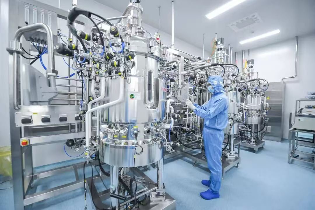
Layout: Installed on the upper side wall of the cylinder. Submerged aeration pipelines extend to the vessel bottom, while surface aeration pipelines remain at upper positions.
Key Points: The sterile boundary covers pipelines between the vessel and filters. Pipelines shall slope toward the vessel to facilitate complete drainage during CIP/SIP processes. Filters shall be mounted as close to the vessel as possible to mitigate contamination risks. Strictly follow installation orientation of flow meters, check valves and filters.
2. Exhaust Module
Function: Balance internal tank pressure and discharge redundant gas.
Composition: Piping sequentially includes optional tail gas condenser, optional heater, filter and pressure regulating valve.
Layout: Located at the top of the vessel.
Key Points: The sterile range spans pipelines from the vessel to filters. Pipelines slope toward the vessel for full drainage in CIP/SIP operations. Filters shall be installed close to the vessel. Downstream pipelines behind filters slope toward discharge outlets. Comply with mounting direction of condensers, heaters and filters.
3. Feeding Module
Function: Deliver liquid raw materials including pH regulators, antifoams, culture media, nutrients and inoculants.
Composition: Composed of flexible hoses, peristaltic pumps and quadruple valve assemblies.
Layout: Mounted on the upper side wall of the cylinder.
Key Points: Sterile area is confined between the vessel and the nearest isolation valve. Quadruple valve assemblies shall be arranged close to the vessel. Pipelines slope toward the vessel to meet CIP/COP and SIP drainage requirements.
4. Harvest Module
Function: Collect finished cultured products.
Composition: Mainly tank bottom valves and connecting pipelines.
Layout: Positioned at the bottom of the vessel.
Key Points: Sterile boundary lies between the vessel and the nearest isolation valve. Equipped with auxiliary CIP/SIP branch valves due to in-situ sterilization of culture medium and long cultivation cycles. Pipelines slope toward discharge ports.
5. Sampling Module
Function: Extract samples during production to monitor cell growth status.
Composition: Consists of sampling valves and sampling bottles.
Layout: Installed on the lower side wall of the cylinder.
Key Points: Sampling valves support both vessel-linked and independent cleaning & sterilization. Sterilize the valve and connecting pipelines prior to sampling, and conduct cleaning after sampling. Isolation valves on upper branches shall be closely fitted to sampling valves to avoid material accumulation. Lower discharge outlets face downward for thorough liquid drainage.
6. CIP/SIP Module
Function: Perform cleaning and sterilization for the vessel and all affiliated units.
Composition: Cleaning fluid pipelines and pure steam pipelines converge into a main pipeline, which diverts branch pipelines to supply cleaning and sterilization media to each functional unit.
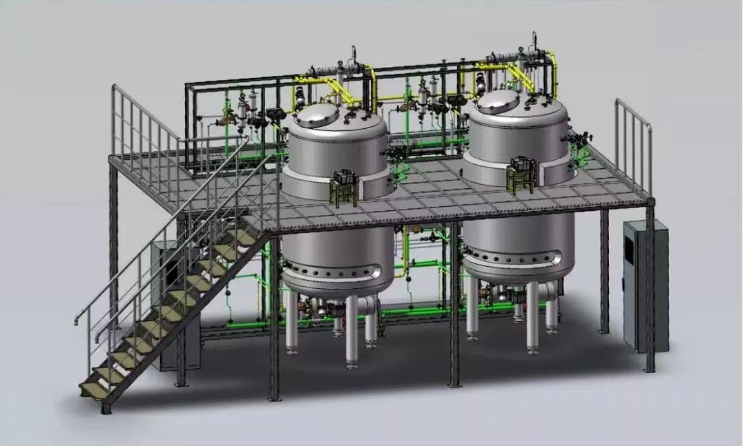
Layout: Preferably arranged at the highest elevation; a low-point drain shall be equipped at the main pipeline terminal if installed at lower positions.
Key Points: All CIP/SIP branch pipelines slope from the main pipeline toward the vessel for residual liquid removal. The main pipeline slopes from the inlet toward the terminal drain outlet.
7. Temperature Control Unit
Function: Regulate internal temperature of culture broth.
Composition: Jacket structure, cooling water piping, steam piping, compressed air piping, jacket circulating water piping, circulation pumps, plate heat exchangers or electric heaters.
Layout: Cooling water enters the jacket bottom and returns from the top; steam feeds into the jacket top and exhausts from the bottom; compressed air injects from the jacket top and drains out at the bottom.
Key Points: Upper branch pipelines connect horizontally or from above, and lower branch pipelines separate horizontally or downward to minimize residual liquid. Adhere to installation direction of circulation pumps, check valves and angle seat valves.
As a leading process-oriented engineering company, Sino Bioengineering delivers professional bioengineering solutions and comprehensive technical services to clients worldwide.
For more products and solutions: https://sinobioengg.com/category/solution/
For more service: https://sinobioengg.com/category/service/