


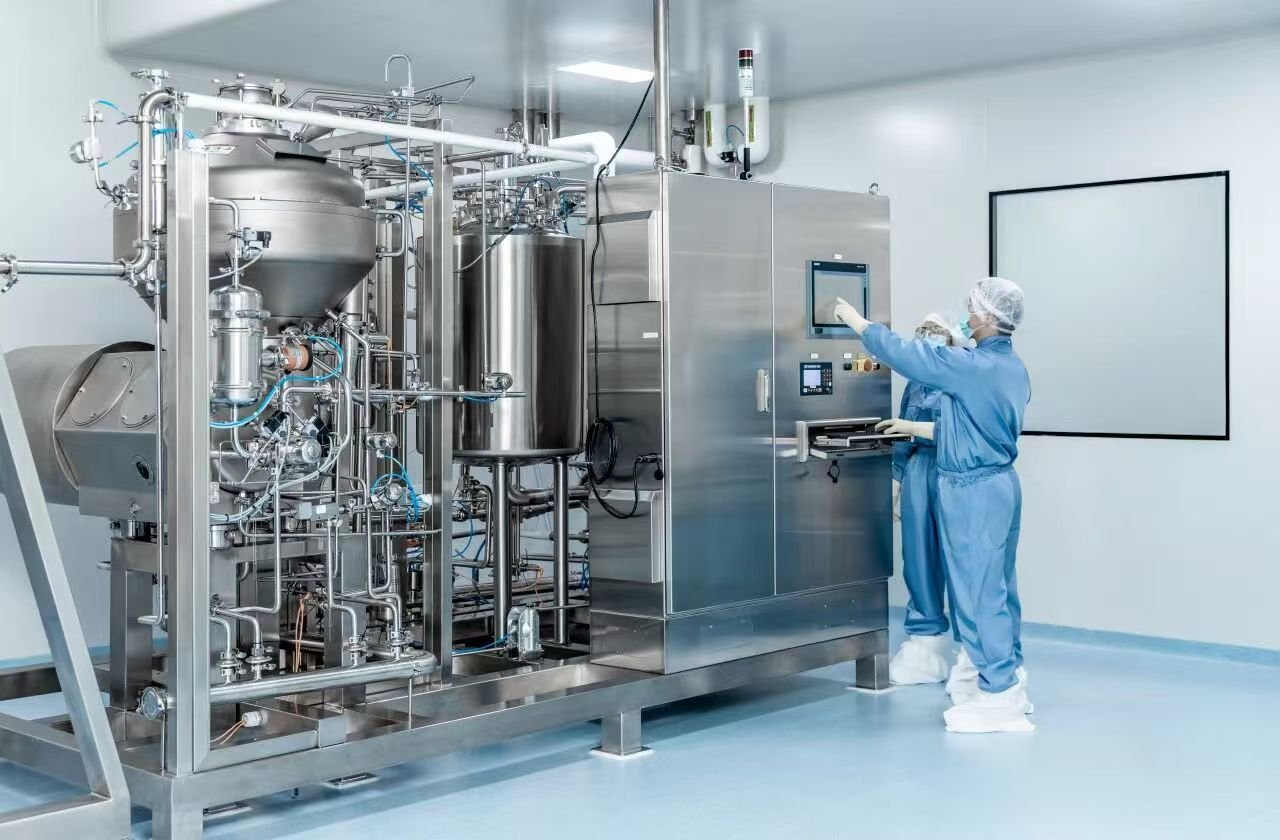
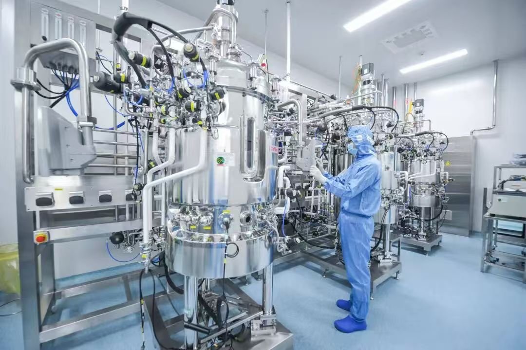
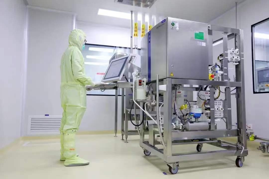
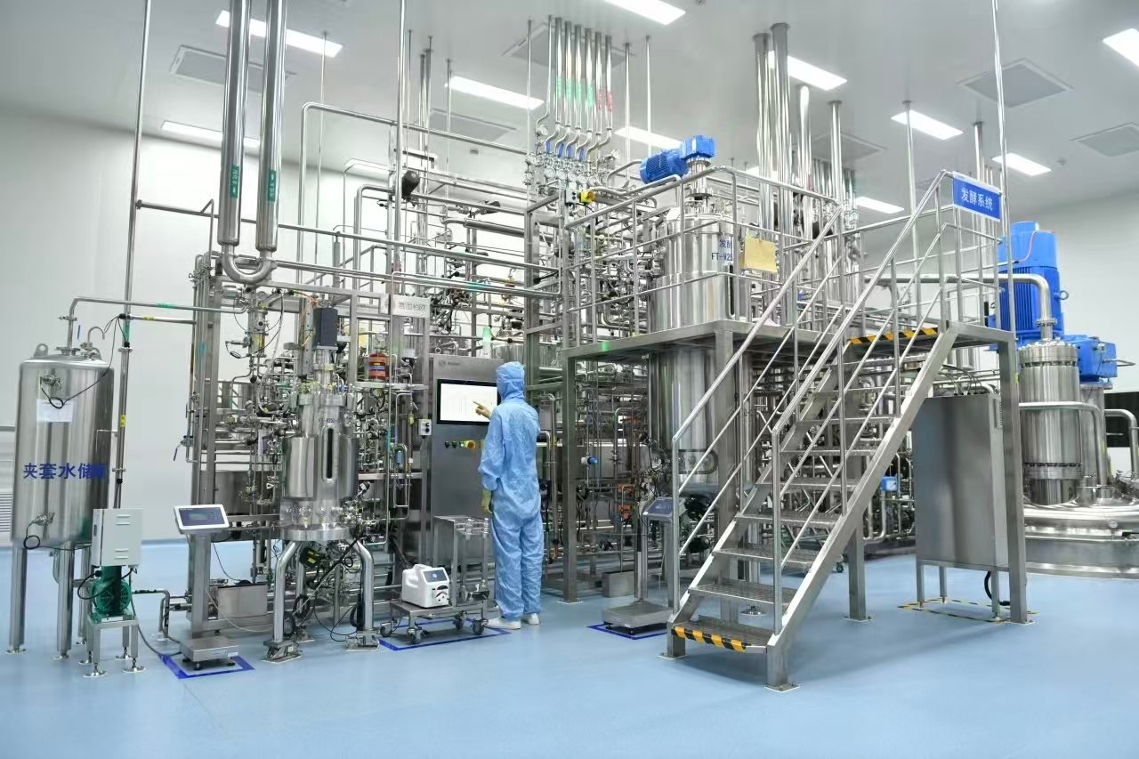
Cleaning-in-Place (CIP) and Sterilization-in-Place (SIP) systems constitute core utility infrastructure in biopharmaceutical manufacturing, underpinning consistent production line operation and product quality assurance. Stringent demands are imposed on cleaning and sterilization efficacy and cycle efficiency. Furthermore, the engineering design and operational status of CIP/SIP systems directly influence manufacturing throughput, cost of goods and product quality. Accordingly, the development of an integrated CIP/SIP design philosophy requires thorough evaluation of process-specific conditions, with particular emphasis on system layout, equipment selection and inherent safety.
1 Overview of CIP and SIP Systems
CIP and SIP systems are widely deployed throughout the biopharmaceutical industry for cleaning and microbial decontamination of process equipment, piping and vessels.
A CIP system removes product residues and soil from wetted surfaces of equipment, piping and vessels by recirculating cleaning solutions without disassembly. Its principal advantage is the ability to execute repeatable, validated cleaning cycles between production batches, minimizing manual intervention, labor cost and equipment downtime.
An SIP system achieves terminal sterilization of process equipment, piping and vessels through the controlled application of saturated pure steam. SIP is designed to achieve a defined bioburden reduction (typically a minimum SAL of 10⁻⁶) by eliminating bacteria, viruses, fungi and spores, thereby safeguarding product safety and quality.
2 Design of CIP and SIP Systems
Several interdependent design elements must be addressed: CIP-specific design, SIP-specific design, system layout and equipment/material selection. A holistic approach is essential to deliver robust, reliable and efficient CIP/SIP systems.
2.1 CIP System Design
CIP is an automated cleaning technology that substantially enhances process efficiency and cleaning consistency while reducing cycle time and operating cost. CIP design shall encompass rational selection of cleaning chemistries, development of validated cleaning recipes, precise control of contact time and temperature, and robust hydraulic circuit design — all directed toward efficient, safe and environmentally sustainable cleaning performance.
2.1.1 Selection of Cleaning Chemistries
Cleaning agents — including alkaline detergents, acidic detergents and oxidative agents — shall be selected based on the wetted materials of construction, soil characteristics and product residue composition. Compatibility with product-contact surfaces and the potential impact on subsequent product quality shall be formally assessed.
2.1.2 Development of Cleaning Recipes
Cleaning recipes shall be developed based on equipment geometry, internal volume and piping configuration. Recipe parameters include the sequence of solution introduction, detergent concentration, solution temperature, contact time and circulation mode (single-pass, recirculating or combination). The recipe shall demonstrate thorough removal of product residues and bioburden from all wetted surfaces to ensure product quality and process safety.
2.1.3 Control of Contact Time and Temperature
Contact time and temperature are critical parameters governing cleaning efficacy and cycle throughput. Contact time shall be determined by equipment size, internal geometry, cleaning agent type and concentration, as well as production scheduling constraints. Solution temperature shall be optimized for detergent efficacy while remaining within the rated limits of all wetted materials and elastomeric components.
2.1.4 Hydraulic Circuit Design
The CIP circulation loop — comprising supply/return piping, pumps and valves — shall be hydraulically designed to ensure turbulent flow and full coverage of all wetted surfaces. The design shall also incorporate cleaning solution recovery, neutralization and waste-treatment provisions to meet environmental compliance requirements. Optimized recovery of cleaning solutions reduces operating cost and environmental load. Flow rate, pressure, spray-ball coverage and drainability shall be evaluated, and the quality of recovered solutions shall be monitored periodically.
2.2 SIP System Design
SIP achieves terminal sterilization of process piping and equipment via saturated pure steam. Design principles encompass steam quality specification, control of steam temperature and pressure, and steam demand calculation to ensure uniform and reproducible sterilization across the entire system.
2.2.1 Steam Specification
SIP systems require pure steam (also termed clean steam) generated from Water for Injection (WFI) or equivalent feedwater, meeting applicable purity requirements for endotoxin, non-condensable gases and dryness fraction.
2.2.2 Control of Steam Temperature and Pressure
Steam temperature and pressure shall be controlled in accordance with the validated sterilization cycle. A typical SIP cycle operates at a minimum of 121 °C (250 °F) corresponding to approximately 1.03 bar(g) saturated steam pressure, with hold time defined by the required F₀ value and bioburden challenge.
2.2.3 Steam Demand and Flow Calculation
Steam demand shall be calculated to ensure adequate steam supply to all sterilization points, accounting for system volume, heat-up load, condensate generation and simultaneous-use factors. Calculations shall incorporate piping dimensions, vessel geometry and detailed component configurations to guarantee uniform temperature distribution and condensate removal throughout the sterilization envelope.
2.3 System Layout
CIP and SIP are critical utility functions in biopharmaceutical and aseptic processing. They enable sequential or simultaneous cleaning and sterilization, improve line efficiency and safety, and reduce the risk of operator error and product contamination.
Layout shall follow the principle of segregated cleaning, sanitization, sterilization and drainage. Storage and distribution of cleaning solutions and sanitizing agents shall be physically segregated; dedicated routing shall be provided for effluent discharge. CIP/SIP equipment itself shall be designed for self-cleaning and self-sterilization to prevent cross-contamination and redundant cycles. Layout shall also prioritize system reliability, intrinsic safety, and ease of operation and maintenance. A thorough process flow assessment and site survey are recommended prior to layout finalization.
Two typical configuration modes may be adopted:
One-to-one configuration: A dedicated CIP/SIP station serves a single process vessel or skid. Logic is straightforward, and independent cleaning/sterilization can be performed without process interference.
One-to-many configuration: A centralized CIP/SIP station serves multiple process vessels or lines. Suitable where process complexity or floor-space constraints preclude dedicated stations. Design must account for peak demand and simultaneous-use factors. This approach reduces capital expenditure but imposes more demanding requirements on automated control and valve matrix interlocking.
Storage and distribution of cleaning solutions and pure steam represent a critical segment of CIP/SIP infrastructure, involving tanks, pump skids and piping networks. Storage vessels shall maintain integrity and prevent ingress contamination. Piping and pump skids shall be routed to deliver cleaning solutions and steam to all target process equipment with adequate coverage. Regulating valves, flow meters and pressure transmitters shall be deployed for closed-loop control and monitoring.
Effluent management is indispensable. Waste streams may contain hazardous or biologically active contaminants; improper handling poses risks to personnel and the environment. In most biopharmaceutical facilities, biologically active effluent is subjected to inactivation (e.g., thermal or chemical) prior to discharge to the sanitary sewer. Discharge and treatment shall comply with applicable regulatory and industrial standards, with dedicated effluent piping, treatment equipment and validated procedures. Safe storage and containment shall be ensured to prevent leakage and secondary contamination.
Reliability shall be embedded throughout layout design — equipment selection and installation, piping routing and connections, and electrical/automation systems — to sustain stable operation. Contingency provisions shall address abnormal scenarios such as equipment failure. Layout shall also facilitate routine operation, inspection and maintenance.
2.4 Equipment and Material Selection
CIP/SIP systems reduce manual cleaning and sterilization workload while safeguarding process hygiene and product safety. Equipment selection is a decisive step directly affecting line performance and product quality and shall be executed with rigorous engineering judgment.
Piping, valves, pumps, heat exchangers, storage vessels and other components shall be selected according to process requirements and adjusted to meet production specifications. Matching instrumentation — including flow meters, temperature transmitters, pressure transmitters and conductivity sensors — shall be deployed for reliable process control. Equipment performance parameters (design pressure, design temperature, flow rate, sterilization compatibility) shall satisfy process demands.
Materials of construction and surface finish are of paramount importance. Since CIP/SIP components undergo repeated chemical and thermal cycling, materials and construction must withstand such conditions. Product-wetted components are typically fabricated from AISI 316L stainless steel (low-carbon grade, per ASME BPE material requirements), offering excellent corrosion resistance and cleanability. Non-product contact utilities (e.g., chilled water, plant steam) may employ AISI 304 stainless steel where justified.
In accordance with ASME BPE guidance:
Product-wetted surfaces shall be mechanically polished and/or electropolished to a defined surface finish — typically Ra ≤ 0.38 μm (15 μin), corresponding to ASME BPE DT-5, with electropolishing applied where enhanced cleanability is required.
Non-contact utility surfaces may be specified at Ra ≤ 0.8 μm (32 μin), corresponding to ASME BPE DT-3.
All wetted surfaces shall be smooth, crevice-free, pit-free and free of cracks.
Dead legs shall be minimized, with the L/D ratio controlled per ASME BPE criteria (typically L/D ≤ 2, not exceeding 3 where process constraints apply).
Piping shall be sloped to drain and self-draining, with no liquid pockets.
Sanitary connections (e.g., tri-clamp, I-Line, orbital-welded joints) shall be used throughout product-wetted systems.
Equipment selection shall also account for system throughput and turndown capability. Production loads vary across operating modes; equipment shall accommodate variable demand to sustain overall efficiency. Preference shall be given to intelligent, integrated equipment with Programmable Logic Controller (PLC) and Supervisory Control and Data Acquisition (SCADA) capability to enable precise control, automated recipe management, electronic data acquisition and audit-trail compliance, minimizing manual intervention.
Safety shall be prioritized throughout CIP/SIP design. Risks such as chemical leakage, steam burns and pressure excursions during storage and transfer shall be mitigated by inherent design and engineered controls. Standard operating procedures and personnel training shall protect operators from accidents attributable to improper handling. Safety considerations encompass equipment operational safety, chemical handling safety (storage, dosing, personal protective equipment) and effluent treatment safety.
3 Application of CIP and SIP Systems in Biopharmaceutical Production
3.1 Layout Case Study
A workshop renovation project at a biopharmaceutical enterprise is presented as a case study. An idle room was converted into a material production area with five newly installed reaction vessels. Floor-space constraints precluded installation of an additional independent CIP/SIP station; however, the existing CIP/SIP station was located immediately across a corridor. Leveraging the existing station, the original two-position three-way pneumatic diaphragm valves were replaced with three-position four-way pneumatic diaphragm valves, and a new CIP/SIP supply/return piping run was routed to the reaction vessels in the renovated area. Interlock logic ensures mutual exclusivity between the new and existing piping circuits. This solution avoids disruption to the original system, satisfies renovation requirements and achieves significant capital savings.
3.2 Engineering Case Study
A CIP/SIP system for a biopharmaceutical workshop comprises storage tanks, alkaline detergent tanks, centrifugal pumps, heat exchangers, filters, sanitary valves, piping and instrumentation. Implementation requires supporting utilities: Purified Water (PW), Water for Injection (WFI), instrument air, plant air, industrial (plant) steam, pure steam, and dedicated effluent/condensate drainage.
Key design notes, aligned with ASME BPE:
1.Materials and surface finish: Vessels and piping in direct product contact adopt AISI 316L stainless steel with electropolished wetted surfaces at Ra ≤ 0.38 μm (ASME BPE DT-5). Non-contact utility piping (chilled water, plant steam, etc.) adopts AISI 304 stainless steel at Ra ≤ 0.8 μm (ASME BPE DT-3).
2.Drainage system: Drain piping and fittings are fabricated from 304 stainless steel. Angle-seat valves are selected for durability and cost-effectiveness. Air breaks (air gaps) are installed upstream of the cleanroom boundary for high-temperature pressurized drainage, pressurized effluent and pressurized alkaline waste streams.
3.Valve selection: Stainless steel PTFE-lined diaphragm valves are employed on product-water and alkaline-solution wetted circuits to meet high hygienic (ASME BPE) requirements.
4.Vent filters and steam traps: When tank vent (breathing) filters undergo pure steam sterilization together with the vessel, the vent-filter electric heat trace shall be activated to prevent condensate accumulation within the filter housing, which could obstruct the cartridge and compromise sterilization efficacy. Thermostatic steam traps are installed on vessel piping, with online temperature monitoring (RTD) at the steam trap discharge to confirm condensate removal and temperature hold.
5.CIP supply pumps:Stainless steel centrifugal pumps are deployed for CIP supply, delivering continuous, stable flow in contrast to pneumatic diaphragm pumps.
6.Monitoring and automation:Online conductivity monitoring is implemented on the CIP return line to verify rinse effectiveness and cleaning endpoint, in accordance with validation requirements. The CIP/SIP system is delivered as a modular skid with PLC-based automated control, online monitoring and electronic batch recording to achieve validated cleaning and sterilization cycles. Modular CIP/SIP stations have been deployed across sterile drug manufacturing workshops. The systems operate stably and comply with Good Manufacturing Practice (GMP) requirements.
4 Conclusion
Biological products are intrinsically linked to human health and life. The widespread deployment of CIP/SIP stations in the biopharmaceutical industry provides robust quality assurance for biomanufacturing. Design engineers shall adopt a multi-faceted approach, develop a thorough understanding of the production process, and embed aseptic design principles — consistent with ASME BPE guidance — throughout the entire pharmaceutical system. Continuous design optimization will drive the biopharmaceutical industry toward higher standards of quality, safety and efficiency.