

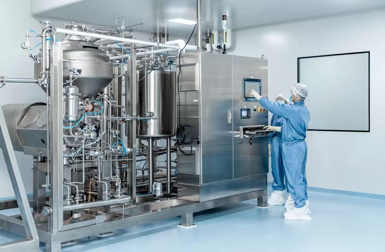
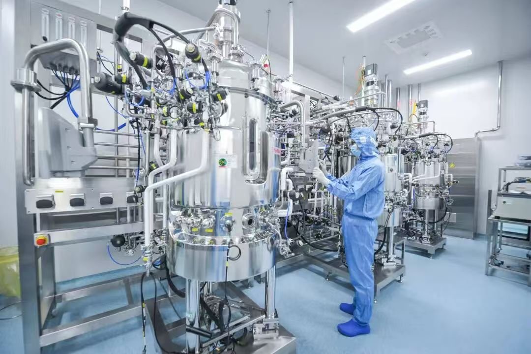
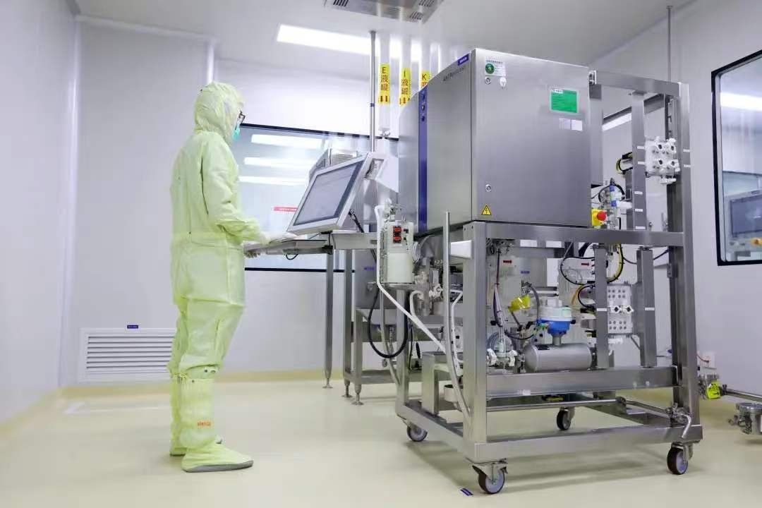

In upstream biopharmaceutical manufacturing, fermenters (bioreactors) represent critical capital production equipment. Stable and reproducible bioprocess performance is fundamentally dependent upon well‑specified, robust instrumentation and control systems. Process instruments function not only as the “sensory hardware” for acquiring process variables, but also constitute the technical foundation for closed‑loop process control, batch‑specific quality traceability, data integrity and regulatory‑compliant manufacturing in accordance with GMP, PIC/S and GAMP‑5 requirements. The scope of measurement spans basic physical parameters (temperature, pressure), core bioprocess electrochemical variables (pH, dissolved oxygen), as well as advanced Process Analytical Technology (PAT) for real‑time biomass and viable‑cell characterization. Rational instrument selection, sanitary mechanical configuration and appropriate loop design directly determine bioreactor process controllability, batch‑to‑batch consistency and final product quality attributes.
This technical guideline systematically elaborates instrument layout, working principles, metrological requirements, key selection criteria, sanitary installation specifications and field‑engineering pitfalls for bioreactor instrument suites. It establishes a comprehensive technical reference for process engineering design, user‑requirement specification (URS) development, equipment tendering, FAT/SAT execution and routine plant‑floor operation & maintenance.
1. General Architecture of Instrumentation Systems
Instrumentation for standard production‑grade bioreactors can be functionally decomposed into seven mutually coupled subsystems: main vessel subsystem, gas supply subsystem, exhaust‑gas subsystem, feed‑addition subsystem, jacket thermal‑control subsystem, utility service subsystem, and sampling‑harvesting subsystem. Co‑ordinated operation of multi‑subsystem instrumentation enables full‑lifecycle multi‑parameter monitoring and interlock protection throughout inoculation, cultivation, SIP/CIP and harvesting sequences.
From the perspective of measured variables, bioreactor‑related instrumentation is categorized as below:
1. Temperature instruments: temperature transmitters, local temperature indicators
2. Pressure instruments: pressure transmitters, local pressure gauges
3. Level / gravimetric measurement instruments: weighing‑module assemblies, differential‑pressure level transmitters
4. Gas‑phase flow instruments: Mass Flow Controllers (MFCs), rotameters, vortex flowmeters
5. Liquid‑phase feed flow instruments: peristaltic dosing pumps, electromagnetic flowmeters
6. Electrochemical sensors: pH electrodes, dissolved‑oxygen (DO) electrodes
7. Foam‑detection instrumentation: antifoam contact probes
8. Process Analytical Technology (PAT): in‑situ Optical Density (OD) sensors, viable‑cell density analyzers
9. Auxiliary instrumentation: level switches, conductivity sensors and other auxiliary field devices
Note: All instruments contacting sterile process media shall comply with biopharmaceutical sanitary design principles including material certification, surface‑finish requirements and cleanability.
2. Temperature‑Measurement Instrumentation
2.1 Online Temperature Transmitters
Temperature is the primary controlled variable for microbial fermentation and mammalian‑cell culture. Measurement points are strategically arranged at four key locations: main‑vessel bulk‑medium temperature, SIP cold‑spot verification point, jacket‑loop temperature (typically at jacket outlet and thermal buffer tank), and utility‑system thermal monitoring points.
Sensing Principle and Selection Criteria: Resistance Temperature Detectors (RTDs) are the dominant sensing element for biomanufacturing applications; thermocouples are rarely adopted due to inferior measurement accuracy and long‑term stability. PT100 and PT1000 are mainstream specifications; PT100 is sufficient for most bioprocess scenarios. Class‑A RTD elements complying with IEC 60751 are recommended. It shall be emphasized that the accuracy grade of sensing elements cannot represent the overall loop‑level measurement uncertainty. Total system uncertainty shall comprehensively consider deviations induced by thermowells, signal transmitters, cable impedance and grounding schemes.
Measurement Span Definition: Upstream bioprocesses operate within a limited thermal operating window. A calibrated measurement range of 0 °C ~ 150 °C fully covers cell‑culture incubation, high‑temperature fermentation and Steam‑in‑Place (SIP) sterilization cycles.
Sanitary Installation Requirements: Measurement points exposed to sterile process fluids (vessel bulk‑medium points, SIP cold‑spot points) shall adopt sanitary‑grade biopharma‑specific connections, including TC‑NA, Neumo Biocontrol, weld‑in sanitary thermowells or matched transition adapters. Conventional threaded connections shall be strictly prohibited from direct contact with sterile process fluids. For non‑sterile circuits such as jacket circulation loops and utility headers, standard threaded mounting is permitted for capital‑cost optimization.
2.2 Local Temperature Indicators
Dedicated stand‑alone local temperature indicators are seldom deployed on modern GMP‑compliant bioreactors. Temperature analog signals are uniformly transmitted to distributed control systems (DCS) or programmable logic controllers (PLC) for centralized visualization, electronic data recording and trend archiving to satisfy data‑integrity requirements.
3. Pressure‑Measurement Instrumentation
3.1 Pressure Transmitters
Pressure transmitters are mainly deployed for bioreactor head‑space pressure monitoring, while vessel‑body additional pressure measuring points are limited. Pressure transmitters installed on steam and compressed‑air headers belong to utility‑system instrumentation rather than bioreactor‑vessel scope.
Range Specification: A measurement span of −1 bar ~ +5 bar is recommended, which must fully cover vacuum operating conditions. Negative‑pressure transients may occur during Clean‑in‑Place (CIP) and SIP thermal cycles; transmitters without vacuum‑range capability will result in measurement failure or irreversible hardware damage.
Engineering Best Practice: Installation of pressure transmitters on utility steam and compressed‑air headers constitutes proven engineering practice, supporting safety interlock logics, alarm triggering and upstream‑process condition validation.
3.2 Local Pressure Gauges
Pressure transmitters undertake real‑time online measurement and signal transmission, whereas local pressure gauges provide indispensable visual on‑site reference for field operators. Typical deployment scenarios include: ‑ Vessel‑side pressure gauge for manual local tank‑pressure observation ‑ Inlet‑gas filter and exhaust filter pressure gauges for differential‑pressure trending to judge filter loading status ‑ Jacket‑loop pressure gauge for circulating‑pressure supervision ‑ Differential‑pressure gauges upstream and downstream of feed filters for fouling‑and‑blockage diagnosis
Installation Note: Where vessel top‑head layout imposes mechanical constraints against direct top‑mounting, the vessel‑pressure gauge may be fitted on the exhaust pipeline with equivalent functional performance.
4. Liquid‑Level and Gravimetric Monitoring
Liquid‑level or gravimetric measurement is a critical bioprocess variable. It provides real‑time working‑volume feedback and serves as the calculation basis for multiple derived parameters including cumulative feed volume, aeration intensity (VVM), and substrate‑concentration calculation. Certain small‑scale R&D bioreactors may omit level‑or‑weight‑sensing hardware; nevertheless, this variable delivers high‑value support for process‑control and batch‑record documentation.
4.1 Gravimetric Weighing Systems
Application Scope: Gravimetric volume measurement is widely implemented for bioreactors with nominal volume ≤ 300 L due to vessel‑geometry constraints.
System Composition: A three‑point support layout with three independent weighing modules, paired with signal transmitters and local indication units, enables accurate total‑vessel mass acquisition.
Accuracy Requirement: C3‑classification weighing modules generally satisfy the metrological requirements of bioreactor upstream processes. Load‑cell protection against thermal radiation, mechanical impact and overloading shall be considered during mechanical design.
4.2 Differential‑Pressure Level Transmitters
Application Scope: Differential‑pressure level transmitters are widely applied in large‑scale industrial production bioreactors. Based on hydrostatic‑pressure principles, liquid height is calculated from the pressure differential between vessel bottom tapping and head‑space reference pressure.
Density‑Compensation Risk Consideration: Measurement fidelity is highly sensitive to fermentation‑broth density variation. Significant measurement drift will occur when actual broth density deviates more than ±5 % from design reference value. Applicability shall be rigorously assessed during URS phase; density‑compensation algorithms or alternative measurement principles shall be adopted where necessary.
Interface Requirements: Bottom‑vessel tapping valves shall follow hygienic design criteria. Bottom‑mounted DRD flanges represent a validated solution satisfying sanitary requirements while facilitating CIP effectiveness and preventive‑maintenance execution.
5. Inlet‑Gas Flow‑Rate Monitoring
Sterile compressed air acts as an essential process feedstock for aerobic bioprocesses. Precise gas‑flow measurement and closed‑loop regulation directly determine dissolved‑oxygen supply capacity and microbial metabolic performance. Three mainstream measurement architectures are applied in industrial projects.
5.1 Rotameters
Operating Principle: Constant‑pressure‑drop variable‑area flowmeters. Upward‑flowing gas passes through a vertically‑oriented tapered tube and lifts the internal float element; float elevation correlates positively with volumetric flow‑rate, which can be read directly from graduated scales.
Technical Characteristics ‑ Advantages: simple mechanical construction, intuitive on‑site readout, low capital expenditure, low pressure drop, wide turndown ratio (~10:1). Suitable for medium‑and‑small flow‑rate conditions below DN150. ‑ Limitations: moderate measurement accuracy (±1.5 % ~ ±4.0 % FS). Readings are influenced by gas density, viscosity, temperature and operating pressure, necessitating process‑condition correction. Float jamming risk exists for particulate‑laden gas streams, imposing strict requirements on inlet‑gas cleanliness.
Installation Requirements: Strict vertical installation with upward‑flow direction is mandatory. Although straight‑pipe‑section requirements are less stringent than vortex flowmeters, upstream straight pipe ≥ 5D and downstream straight pipe ≥ 3D are recommended to stabilize flow‑field distribution.
5.2 Mass Flow Meters and Mass Flow Controllers (MFCs)
Operating Principle: Mass Flow Meters (MFMs) directly measure gas mass flow. Output readings (e.g., sccm, slm) are normalized to standard reference conditions (0 °C, 101325 Pa), hence largely immune to fluctuations of operating pressure and temperature. Built‑in temperature compensation corrects gas‑property variations to guarantee metrological performance.
MFC vs. MFM: A Mass Flow Controller (MFC) integrates a modulating control valve on the basis of MFM to form closed‑loop flow regulation, stabilizing flow at user‑defined set‑points. MFCs are extensively deployed on laboratory‑scale and mid‑size bioreactors.
Thermal‑Type MFC (Industry Mainstream): Adopts thermal‑diffusion measurement principle. Gas flowing over heated sensors dissipates heat; mass‑flow magnitude is derived from temperature differential or heating‑power consumption. Compact mechanical structure, yet response time is at second level. Measurement performance depends on gas specific‑heat capacity and is sensitive to gas‑composition changes. Liquid ingress, oil contamination and particulate deposition must be strictly excluded; compressed‑air supply shall be equipped with drying devices to secure inlet‑gas quality.
Laminar Differential‑Pressure MFC: Operates based on Poiseuille’s law. Gas flows through laminar‑flow elements generating pressure drop proportional to mass‑flow magnitude. Combined with temperature‑sensor compensation, it delivers high accuracy and wide turndown ratio.
5.3 Vortex Flowmeters
Operating Principle: Karman vortex‑shedding principle is adopted. A bluff‑body vortex generator installed in flow path generates alternating downstream vortices; vortex‑shedding frequency has linear correlation with fluid velocity for flow‑rate calculation.
Technical Characteristics and Application: Robust structure with no moving parts, high operational reliability and wide turndown ratio, compatible with gas, steam and liquid media. Sanitary‑grade vortex flowmeters complying with 3‑A standards and high‑surface‑finish specifications are widely used for sterile‑air and steam‑header flow measurement on large‑scale production bioreactors.
Installation Requirements: Demanding for straight‑pipe sections; upstream straight‑pipe length of 10D ~ 50D is generally required. The instrument shall be installed upstream of control valves to avoid flow‑field distortion caused by valve throttling effects.
6. Feed‑Stream Flow‑Rate Monitoring
Fed‑batch feeding is one of the core process‑control strategies for bioreactor cultivation. Precise feed‑volume metrology is critical for stabilizing substrate concentration and maximizing target‑product titre.
6.1 Peristaltic Dosing Pumps
Application Scope: Widely applied for low‑flow‑rate, high‑precision feeding scenarios. Model selection shall refer to original‑equipment‑manufacturer (OEM) performance datasheets.
Selection Considerations: Variable‑speed peristaltic pumps are preferred for bioreactor feeding to satisfy variable feed‑rate demands across different cultivation phases. Peristaltic pumps demonstrate linear response to feed‑material density for most bioprocess feeds, achieving satisfactory metrological performance without additional feed‑weighing hardware. Pump tubing is a consumable component and shall be replaced batch‑wise or according to predefined preventive‑maintenance schedules. For corrosive feed formulations, fluoropolymer‑elastomer tubing or other specialty materials shall be specified in consultation with vendors.
Installation Configurations: Peristaltic pumps can be skid‑integrated onto bioreactor assemblies, or deployed as freestanding units for seed‑culture inoculation or discrete bulk‑feed addition.
6.2 Flowmeter‑Based Dosing Architectures
For high‑flow‑rate feeding in large‑volume bioreactors, modulating control valves matched with flowmeters constitute mainstream configuration. Electromagnetic flowmeters are applicable for conductive liquid feeds, featuring high measurement accuracy, negligible pressure loss and convenient maintenance.
7. pH and Dissolved‑Oxygen Monitoring
pH and dissolved‑oxygen (DO) are the most critical electrochemical variables in upstream bioprocesses. Sensor technology is commercially mature. Major global suppliers include Mettler‑Toledo and Hamilton, alongside qualified domestic manufacturers.
7.1 pH Electrodes
Two mainstream types are available: liquid‑fill and gel‑fill electrodes. Liquid‑fill electrodes deliver fast response and superior accuracy for high‑precision measurement scenarios. Gel‑fill electrodes feature lower maintenance workload and longer service life for routine production applications.
ORP Integration: Combined pH‑ORP electrodes are available when oxidation‑reduction potential (ORP) monitoring is required. Nevertheless, dedicated standalone ORP sensors are recommended for GMP‑regulated production vessels requiring high ORP‑measurement reliability.
7.2 Dissolved‑Oxygen Electrodes
Polarographic and optical DO electrodes are commercially available. Optical DO sensors represent the prevailing modern‑industry solution, with advantages including low‑maintenance requirements, zero electrolyte consumption, fast dynamic response, and immunity to toxic interfering substances such as hydrogen sulfide.
Insertion‑Length Specification: 120 mm insertion depth satisfies most standard‑size bioreactors. For large‑volume production bioreactors, longer sensor variants (225 mm, 325 mm or custom‑length options) shall be selected according to vessel internals geometry.
7.3 Key Engineering Implementation Specifications
‑ Sensor‑cable Management: Purpose‑built high‑temperature‑resistant, SIP‑compatible, shielded sensor cables are mandatory. On‑site splicing or arbitrary extension of sensor cables is strictly forbidden. Actual routing distances from vessel sensor ports to transmitters and control cabinets shall be validated during URS phase, to prevent signal attenuation induced by insufficient cable length or excessive redundant cabling. ‑ Redundant‑Sensor Configuration: For high‑value‑product manufacturing, dual pH and dual‑DO sensor installation is a widely‑adopted risk‑mitigation strategy. It enables primary‑backup redundancy and cross‑sensor validation, improving monitoring reliability and supporting deviation investigation. ‑ Standard Mechanical Interfaces: Bioprocess‑grade electrodes adopt PG13.5 male threads, mating with 12 mm Ingold‑style sanitary vessel ports. Hermetic sterile sealing is realized by threaded compression combined with O‑ring gaskets; this represents the de‑facto industry‑standard interface for upstream bioreactors.
8. Foam‑Detection Instrumentation
Antifoam contact probes detect foam‑layer height. Once foam contacts the probe surface, antifoam‑agent dosing will be triggered or hardware‑level alarms activated.
Application Characteristics: Foam‑sensing probes are more frequently adopted in laboratory‑scale R&D bioreactors. Deployment is less common for large‑scale commercial manufacturing. Larger‑volume vessels adopt conservative filling ratios; foaming risk can be effectively mitigated by process‑parameter tuning of agitation speed and aeration set‑points.
Regulatory‑Compliance Risk Assessment: Reliance on antifoam‑agent addition as primary foam‑control measure is discouraged under GMP regulatory frameworks. Two core risks exist: first, complex antifoam formulations may introduce uncharacterized impurities, imposing potential adverse impacts on product quality; second, dosing quantity and trigger timing are difficult to precisely control, bringing about uncontrolled process‑variability risks. Process‑optimization strategies and mechanical‑defoaming hardware shall be prioritized for foam‑suppression solutions.
9. Process Analytical Technology (PAT)
Driven by biopharma‑industry digitalization and intelligent‑manufacturing transformation, PAT instruments are increasingly implemented on bioreactor assets. Spare vessel nozzles shall be reserved during basic‑engineering phase to accommodate diverse in‑situ analytical sensors beyond conventional process‑variable instrumentation.
9.1 In‑situ Optical Density (OD) Sensors
Functional Overview: Achieves real‑time, aseptic, in‑situ total‑cell‑density measurement. Supports biomass‑growth trending, feed‑rate adjustment and end‑of‑fermentation judgment.
Technical Limitations: Relatively high capital investment. Biofouling accumulation over long‑duration cultivation cycles may cause measurement drift, whose magnitude is highly process‑dependent.
Typical Industrial Deployment: OD sensors installed on seed bioreactors support automated culture transfer upon reaching predefined biomass thresholds, realizing efficient automated process workflows.
9.2 Viable‑Cell‑Density Analyzers
Functional Overview: Real‑time in‑situ quantification of viable‑cell concentration. Measurement outputs remain insensitive to media‑composition variation, microcarrier existence, dead‑cell populations and cellular debris. Widely applicable for mammalian‑cell culture, yeast fermentation and high‑density bacterial bioprocesses. Real‑time process feedback can be obtained without manual destructive sampling.
Application Positioning: High‑capital‑cost analytical instruments, mostly deployed for trend‑monitoring purposes and providing datasets for process‑optimization activities.
9.3 Off‑Gas Analyzers
Off‑gas analyzers belong to standalone analytical equipment instead of vessel‑mounted field instruments. They quantify exhaust‑gas O₂ and CO₂ concentrations for calculating key metabolic parameters: Oxygen Uptake Rate (OUR), Carbon‑Dioxide Evolution Rate (CER) and Respiratory Quotient (RQ). In‑depth discussion is beyond the scope of this document and will be covered in dedicated follow‑up technical documentation.
10. Supplementary Instrumentation
10.1 Level Switches
Where buffer tanks are integrated within jacket thermal‑control circuits, level switches shall be configured for low‑liquid‑level alarming and interlock protection, eliminating circulating‑pump dry‑run failure modes.
10.2 Conductivity Sensors
Conductivity sensors are commonly installed on CIP return‑flow circuits to determine cleaning‑cycle endpoint. Where mounted on bioreactor bottom nozzles, sanitary‑grade process connections shall be specified.
10.3 Agitator Rotational Speed
Dedicated shaft‑mounted speed sensors are rarely fitted for bioreactor agitators. Rotational‑speed feedback is almost universally obtained from variable‑frequency‑drive output telemetry signals.
10.4 Double‑Mechanical‑Seal Assemblies
Selected complex bioreactor configurations adopt double mechanical seals equipped with barrier‑fluid circulation loops, fitted with auxiliary temperature‑and‑pressure monitoring instruments. Further detailed description is omitted within this guideline.
Conclusion
Bioreactor instrumentation systems constitute integrated multi‑variable measurement‑and‑control ecosystems. From basic temperature‑pressure sensing loops, core pH‑DO control architectures to advanced PAT‑enabled in‑situ analytics, instrument selection and mechanical configuration require holistic risk‑based evaluation combining process‑specific operating conditions, production‑scale attributes and regulatory‑compliance obligations.
This guideline delivers a comprehensive structured technical reference framework. Practical engineering implementation shall carry out application‑specific assessment oriented to individual‑process characteristics. Final instrument specifications, loop design and sanitary‑installation schemes shall be jointly reviewed and technically validated with qualified OEM vendors. As the biopharmaceutical industry evolves toward continuous biomanufacturing and intelligent manufacturing paradigms, bioreactor‑instrumentation hardware will feature higher system integration, enhanced operational robustness and expanded data‑analysis capability, providing solid technical support for high‑quality, cost‑effective biomanufacturing.