


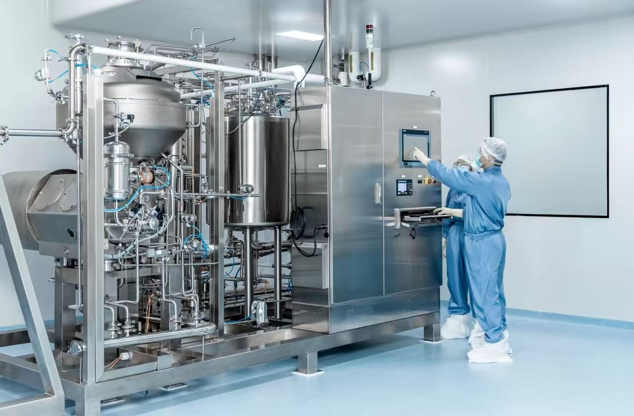
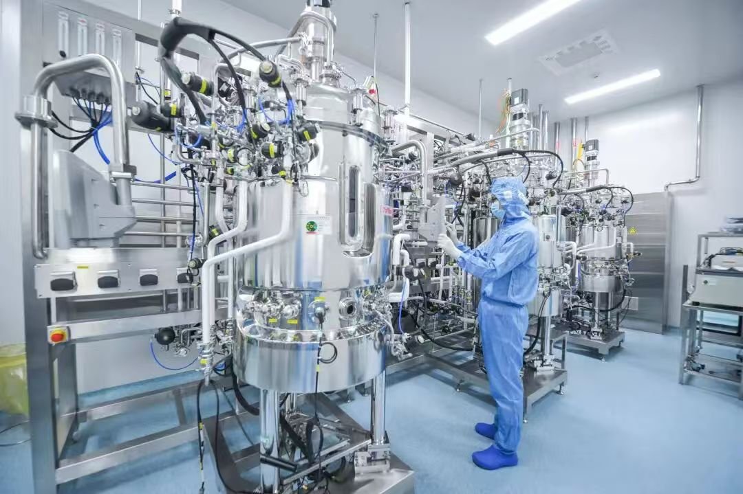
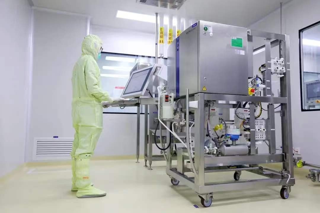
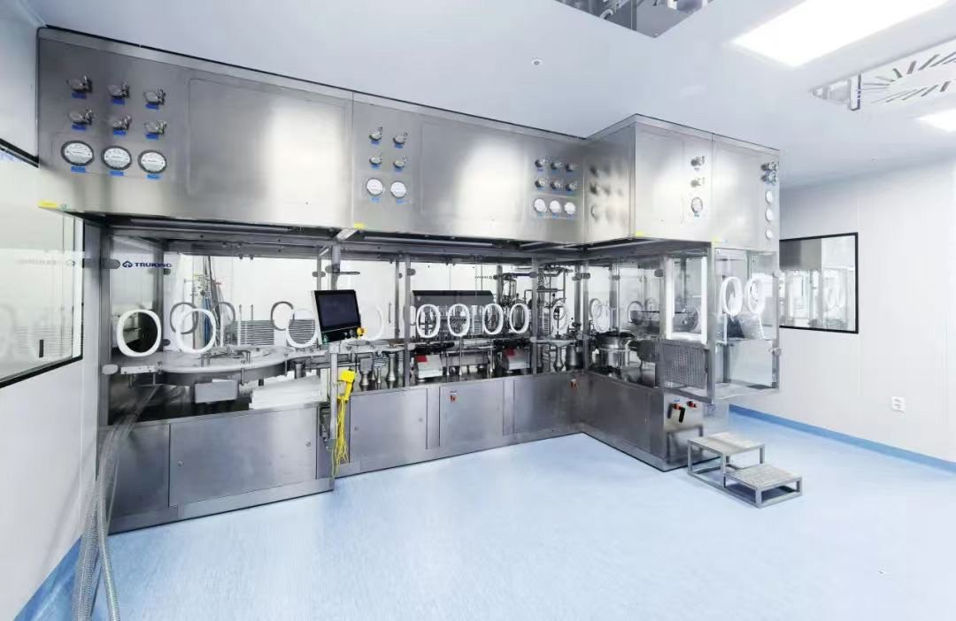
Class A (ISO 5) unidirectional laminar flow serves as the primary sterile barrier in highest-risk operation areas for sterile pharmaceutical manufacturing (filling, sterile connection, open vial filling, etc.). The airflow pattern visualization test (smoke study) constitutes a mandatory verification activity to confirm the effectiveness of unidirectional flow protection and establish the Contamination Control Strategy (CCS). The 2026 revised Chinese GMP Annex for Sterile Medicines, EU GMP Annex 1 (2022), FDA Guidance for Industry on Sterile Drug Product Production, USP <797>/<800> and ISO 14644-3 form an integrated compliance control framework. Uniform requirements mandate both static and dynamic visualization tests; verification relying solely on no-load static conditions is prohibited. Quantified acceptance criteria are defined for tracers, air velocity, video archiving, recovery time and streamline morphology. Meanwhile, hierarchical root cause analysis and systematic rectification schemes are provided for non-conforming airflow patterns including eddies, reverse flow, dead zones, uneven air velocity and airflow short-circuiting. This paper elaborates on nine dimensions: regulatory benchmarking, test equipment selection, standardized test protocols, full-scenario test locations, compliance acceptance criteria, overall process control considerations, root causes of typical airflow pattern defects, hierarchical rectification implementation plans, and closed-loop management of validation documentation. It covers all application scenarios including cleanroom laminar flow hoods, Class A laminar flow ceilings for filling lines, RABS and Class A unidirectional flow zones within isolators.
2 Benchmarking of Mandatory Core Requirements for Class A Laminar Flow Airflow Pattern under Three Major Regulatory Systems
2.1 Revised Chinese GMP Annex 1 (Sterile Medicines, formally implemented clauses in the 2026 draft for public consultation)
Articles 77 and 80 explicitly specify airflow pattern study as a mandatory confirmation activity during IQ/OQ/PQ for unidirectional flow systems. Differentiated from the old version which only required static visualization, new mandatory constraints are introduced:
1.Both static tests (unoccupied, no-load equipment operation) and dynamic tests (simulation of complete production interventions, personnel operations, full-speed equipment operation) shall be performed concurrently. Dynamic testing forms the core of validation, while static testing only serves as baseline reference.
2.Tracing media shall be neutrally buoyant, non-toxic, residue-free and non-contaminating to clean areas. Oil-based smoke sticks and high-temperature smoke are forbidden; medical-grade ultrasonic water mist generators are preferred.
3.High-definition video recordings shall be retained throughout the test with embedded system timestamps, uneditable and permanently archived. Videos shall fully capture the entire trajectory of smoke from HEPA supply surfaces to air return zones.
4.The statutory air velocity range within the Class A unidirectional flow working zone is 0.36–0.54 m/s with air velocity uniformity ≤0.25. The deviation angle of airflow streamlines from vertical shall be less than 14°. Airflow pattern test results shall be assessed in correlation with air velocity data.
5.Airflow pattern results shall be directly incorporated into the Contamination Control Strategy (CCS) to support definition of environmental monitoring sampling points, personnel intervention SOPs and equipment layout optimization.
6.Special airflow pattern tests shall be carried out for cross-area openings (pass-through windows and discharge ports connecting Class A with Class B/C) to demonstrate no risk of backflow of air from lower cleanliness zones.
2.2 EU GMP Annex 1 (2022, current EU sterile pharmaceutical regulation)
Clauses 4.30 and 4.31 constitute the core basis for Class A unidirectional flow airflow pattern testing. Missing dynamic testing ranks among the most frequent observations during EMA on-site inspections:
1.The primary objective of unidirectional flow visualization testing: to demonstrate that airflow travels exclusively from high-cleanliness Class A zones towards lower-cleanliness zones, without upward recirculation from floors, equipment or personnel bodies, and without eddies trapping contaminants.
2.Air velocity of 0.36–0.54 m/s serves as a guidance value. If an enterprise adopts air velocity outside this range, comprehensive scientific risk justification shall be provided within the CCS.
3.Dynamic testing shall simulate worst-case conditions: simultaneous operations by multiple personnel, reciprocating mechanical movements of equipment, frequent opening and closing of hatches/cleanroom doors, and continuous material transfer.
4.For semi-enclosed Class A zones within isolators and RABS, additional verification shall be performed on positive/negative pressure barriers of the enclosure to prevent penetration of external air through the unidirectional flow barrier.
5.The test frequency shall align with HVAC revalidation. Full airflow pattern studies shall be conducted at intervals no longer than 12 months for high-risk filling Class A zones. Immediate retesting is required following major modifications or HEPA filter replacement.
2.3 FDA Guidance for Industry on Sterile Drug Product Production and 483 Observation Criteria
FDA cGMP imposes stricter operational constraints on Class A laminar flow airflow pattern testing. Recurring observations in FDA 483 letters and warning letters include exclusive reliance on static testing, incomplete video recordings and failure to simulate realistic interventions:
1.In situ smoke studies shall cover all critical locations exposed to products. First Air zones such as filling needles, stopper bowls, open vials and sterile connection joints are mandatory test locations.
2.Dynamic simulation requirements: operators shall perform a full set of standard intervention actions within the Class A zone (reaching for components, surface wiping, jammed vial clearance, material feeding), with hands approaching within a minimum distance of 15 cm from product exposure points to verify airflow recovery capacity after disturbance.
3.Hard acceptance criteria: following airflow disturbance by personnel or equipment, laminar flow recovery time shall be ≤20 seconds. No eddies or reverse flow shall overlay critical product zones prior to full recovery.
4.Successful HEPA PAO leak testing alone is insufficient to demonstrate unidirectional flow effectiveness; supporting airflow pattern visualization testing is mandatory. Local air velocity imbalance across filters directly results in non-conforming airflow patterns.
5.Raw video files shall remain uncompressed and unedited, and inspectors may access historical test recordings for full traceability of validation activities.
6.Tracers shall not alter original airflow trajectories. Smoke generators must not block supply surfaces or disrupt laminar flow velocity. High-volume smoke jetting into the unidirectional flow system is prohibited.
2.4 Supporting Standards
ISO 14644-3:2005 Cleanrooms and associated controlled environments — Part 3: Test methods, Appendix B.12, GB/T 25915.3 and T/TPPA 0011-2025 Specification for Visualization Test of Unidirectional Airflow in Pharmaceutical Cleanrooms standardize test operations, equipment and acceptance boundaries, providing technical implementation support for the three regulatory frameworks above.
3 Equipment Selection and Compliance Requirements for Full Set of Class A Laminar Flow Airflow Pattern Test Equipment
3.1 Tracer Smoke Generators (Core Compliance Equipment)
Regulations explicitly prohibit oil-based smoke sticks and high-temperature chemical smoke. Only two types of neutrally buoyant tracing equipment are permitted:
1.Ultrasonic Water Mist Generator (Preferred, compliant for all zones) Media: Water for Injection (WFI), droplet size 0.5–1 μm, neutrally buoyant, residue-free, non-chemically contaminating and non-clogging to HEPA filters. Adjustable smoke output and multi-hole extended smoke delivery tubes enable uniform linear smoke release, suitable for large-area Class A ceilings, large filling laminar flow hoods and internal RABS spaces.
2.Pharmaceutical-grade Propylene Glycol Cold Fog Generator (Isolator-only) Only applicable to enclosed Class A zones inside isolators. Fog fully vaporizes without condensed residue. Usage on open laminar flow ceilings is forbidden, as it may cause water stain contamination on stainless steel surfaces. Prohibited equipment: pyrotechnic smoke sticks, diesel smoke, dry ice smoke (excessive mass causes sedimentation leading to distorted airflow trajectories; not accepted by FDA).
3.2 Auxiliary Test Equipment
1.Calibrated anemometer: accuracy ±0.01 m/s, subject to annual metrological calibration, for measuring air velocity across HEPA supply surfaces and working zone grids.
2.High-definition camera system: 4K resolution, embedded timestamp watermark, frame rate ≥30 fps, equipped with side-mounted light sources (45° oblique cool white light to enhance smoke contrast; matte black background panels improve visualization performance).
3.Differential pressure recorder: continuously records pressure differential between Class A and adjacent Class B zones and pass-through windows to monitor pressure fluctuations throughout testing.
4.Mobile height-adjustable smoke delivery stands: eliminate human interference errors caused by manually holding smoke tubes and avoid airflow obstruction.
5.Temperature and humidity monitor: Class A environmental conditions controlled at 18–26 °C, RH 45%–65%. Significant fluctuations in temperature and humidity alter mist buoyancy and interfere with airflow pattern assessment.
3.3 Documentation Equipment
Approved test protocol, raw data record sheets, tamper-proof video archive server, airflow pattern image analysis reports, deviation handling records.
4 Standardized Complete Operational Procedure for Class A Laminar Flow Airflow Pattern Testing
Testing shall strictly follow a five-step workflow: pre-test qualification → static full-location testing → dynamic worst-case simulation testing → data and video archiving → result assessment. All steps shall be continuously recorded on video.
4.1 Pre-Test Qualification (Testing prohibited if unsatisfactory)
Smoke studies shall only commence after satisfactory completion of the following pre-tests; otherwise, airflow pattern data will be deemed invalid and unacceptable to regulatory authorities:
1.HEPA filter PAO integrity leak test: no leakage; no penetration defects on filter frames and sealing gaskets.
2.Grid air velocity testing: working zone air velocity maintained at 0.36–0.54 m/s, one measurement point per 0.6 m² across full HEPA ceilings; air velocity uniformity ≤0.25.
3.Zonal differential pressure: Class A maintains a positive pressure of 10–15 Pa relative to Class B. Stable bidirectional differential pressure across pass-through windows without instantaneous negative pressure fluctuations.
4.HVAC/FFU systems run at full load for a minimum of 30 minutes for self-purging; airborne particles meet Class A static limits.
5.Environmental temperature and humidity stabilized within compliant ranges; cleanroom floors and equipment surfaces remain dry without standing water.
6.All test equipment within valid calibration periods; smoke generators cleaned and disinfected in advance to avoid foreign contaminants.
4.2 Static Airflow Pattern Testing (No-load Baseline Testing)
Static condition definition: HVAC and laminar flow fans operate at full speed, production equipment remains stationary without load, no personnel enter the Class A zone, only fixed tooling and standard moulds remain in place.
1.Smoke release location coverage requirements
• Supply surface testing: Smoke evenly released along the lower edge of each HEPA filter to verify uniform vertical downward airflow across the entire ceiling, free of local smoke plumes and dead air zones.
• Equipment windward surface testing: Smoke released above all protruding structures including filling supports, conveyor tracks, stopper hoppers and isolator inner walls to observe airflow bypass morphology.
• Boundary locations: Specific smoke testing at Class A enclosure edges, above air return grilles, pass-through window openings and gaps on partition walls separating Class A and Class B zones.
• Critical operation locations: filling needle stations, open vial placement zones and sterile connection platforms serve as primary observation points.
2.Standard operating specifications Smoke delivery tubes run parallel to HEPA supply surfaces and move slowly and continuously. Smoke volume shall be moderate; excessive mist obscures streamlines. Simultaneous recording via panoramic fixed cameras and close-up cameras for each location for a minimum of 3 minutes. Smoke shall travel vertically downwards smoothly and flow into bilateral floor air return grilles without stagnation, turbulence or rebound.
4.3 Dynamic Airflow Pattern Testing (Mandatory Core Verification per Regulations)
Dynamic testing simulates worst-case actual production conditions and constitutes the decisive basis for assessing sterile risks. Validation is deemed invalid without dynamic testing.
1.Simulated operating conditions (to be fully documented in the test protocol and implemented item by item) (1) Personnel arrangement: Production operators in full sterile gowning enter the Class A zone and perform complete intervention sequences. (2) Equipment operating conditions: Filling machine runs continuously at full speed with rotating vials and reciprocating manipulators in continuous motion. (3) Personnel intervention actions: Hands approach within 10–15 cm of product exposure points for component handling, surface wiping, jammed stopper clearance and sterile tubing connection. (4) Material transfer: Frequent opening and closing of pass-through windows and continuous material movement into and out of the Class A zone. (5) Boundary disturbances: Temporary opening of cleanroom doors, hatch operation of RABS and continuous product discharge through outlet channels.
2.Core observation indicators for dynamic testing Following airflow disturbance by personnel arms or moving equipment components, smoke rapidly restores vertical unidirectional flow within 20 seconds. Eddies generated during disturbance shall not overlay critical product exposure zones. No floor dust shall be entrained by upward recirculating airflow.
4.4 Special Airflow Pattern Testing for Cross-Zone Barriers (Key Inspection Focus for EU and FDA)
Independent testing for connecting openings between Class A and lower-cleanliness zones: Smoke is released on the low-class side of pass-through windows and discharge ports to observe potential smoke infiltration into Class A zones. Acceptance criterion: Smoke is fully blocked by positive-pressure unidirectional flow within Class A without cross-boundary backflow; airflow continuously travels from Class A towards Class B/C zones.
5 Quantified Acceptance Criteria for Class A Laminar Flow Airflow Patterns (Unified Standards for China, EU and FDA)
5.1 Qualitative Criteria for Streamline Morphology
1.Static conditions: Smoke forms parallel vertically downward unidirectional streamlines across all zones, free of random turbulence, local smoke cloud stagnation, upward recirculation and dead zones. Airflow bypasses equipment obstructions smoothly without recirculating eddies downstream of obstacles.
2.Dynamic conditions: Personnel and equipment disturbance only generate transient minor local turbulence. Uniform laminar flow fully recovers within 20 seconds after disturbance ceases. Continuous clean First Air covers critical product locations throughout disturbance events.
3.Zonal airflow direction: Airflow consistently travels from high-cleanliness Class A zones towards air return systems and adjacent lower-cleanliness zones; no reverse penetration of air occurs.
5.2 Mandatory Quantified Indicators
1.Working zone air velocity: 0.36–0.54 m/s; air velocity deviation within individual HEPA filters ≤±25%.
2.Maximum deviation angle of airflow streamlines from vertical: <14°.
3.Laminar flow recovery time after disturbance: ≤20 s.
4.No persistent eddy zones or airflow short-circuiting (air supply directly impinging on air returns without covering work surfaces).
5.No backflow of lower-class air across openings.
6 Compliance Considerations Throughout the Test Process (Avoiding Top Regulatory Observations)
6.1 Control of Tracers and Smoke Generation Operations
1.Strictly avoid excessive smoke: Excessive water mist condenses on stainless steel surfaces and creates microbial retention risks; insufficient smoke fails to fully demonstrate airflow trajectories, leading inspectors to judge inadequate testing coverage.
2.Smoke delivery tubes shall not extend underneath critical operation surfaces or block HEPA supply air. Smoke stands shall not create additional airflow obstructions.
3.After testing completion, laminar flow systems shall run continuously for 30 minutes to purge residual mist. Surfaces and equipment shall be wiped dry, and cleaning activities documented.
6.2 Mandatory Compliance Requirements for Video Recording
1.Continuous uninterrupted recording without pause, editing or segmented splicing; video embedded with system timestamps accurate to the second.
2.Dual-camera recording: panoramic camera fully covering the entire Class A zone, close-up camera focusing on critical locations such as filling and connection stations.
3.Video files archived in encrypted form with retention period no less than 5 years after product expiry date, aligned with FDA ALCOA+ data integrity principles.
4.Supporting written records for video files: documenting test scenarios, smoke release locations, operators, equipment operating status and test start/end timestamps.
6.3 Environmental and Personnel Control Measures
1.No irrelevant personnel shall enter adjacent clean areas during testing to minimize pressure fluctuations induced by door operation.
2.Operators shall avoid rapid hand movements and large limb gestures to prevent artificially generating extra turbulence and skewing test results.
3.Differential pressure monitored continuously throughout testing. Testing shall be suspended immediately if instantaneous pressure fluctuation exceeds 5 Pa; resume testing only after troubleshooting HVAC faults.
4.No idle materials or turnover boxes shall be stacked within the Class A zone. Layout during testing shall match full-scale production configuration; temporary removal of equipment to conceal eddy defects constitutes a typical FDA 483 observation.
6.4 Test Frequency and Retrigger Conditions for Retesting
1.Scheduled revalidation: Full airflow pattern testing every 12 months for high-risk filling Class A zones; every 24 months for low-risk sterile filling Class A zones, aligned with HVAC system PQ activities.
2.Mandatory full retesting (complete static + dynamic airflow pattern testing required if any of the following occurs):
• Full/partial replacement of Class A ceiling HEPA filters, plenum modification or FFU fan replacement.
• Cleanroom layout adjustment, relocation of filling equipment or installation of large additional support structures.
• HVAC duct modification, addition or removal of air returns, adjustment of differential pressure setpoints.
• Occurrence of sterile deviations, sustained airborne particle excursions or microbial contamination incidents.
• Retesting following rectification of airflow pattern-related observations raised during regulatory inspections.
• Major adjustment of laminar flow fan frequency parameters or supply air volume.
6.5 Documentation and Record Compliance
Test protocols require joint review and approval by Quality, Engineering, Production and Validation departments. Raw data entries completed in real time with corresponding video reference numbers annotated. Airflow pattern reports shall include smoke screenshots, streamline analysis, risk assessment and formal acceptance conclusions. Non-conforming airflow patterns trigger deviation procedures with complete documentation of root causes, corrective actions and retest data.
7 Typical Non-Conforming Airflow Patterns for Class A Laminar Flow, Root Causes and Hierarchical Rectification Plans
Airflow pattern non-conformities are categorized into five groups: inherent design defects, hardware equipment failures, operational parameter imbalance, inappropriate operational layout and failed differential pressure barriers. Rectification follows a four-stage progressive approach: interim control → hardware modification → parameter optimization → SOP governance. Upon completion of rectification, full-location static and dynamic airflow pattern retesting shall be performed until all acceptance criteria are met.
7.1 Defect 1: Persistent Eddies Downstream of Equipment Obstructions (Most Frequent Observation)
1.Phenomenon: Filling columns, manipulator supports, stopper hoppers and conveyor tracks positioned directly beneath HEPA filters create persistent recirculating smoke clouds downstream of equipment. Eddy zones expand under dynamic conditions and may envelop product exposure points.
2.Root cause: Large windward equipment cross-sections create low-pressure eddy zones as vertical unidirectional flow bypasses obstacles; particles and microorganisms become trapped and cannot be purged by airflow.
3.Hierarchical rectification measures
• Short-term interim control: Relocate equipment towards air return sides to reduce obstructions directly beneath supply surfaces; increase local FFU air velocity to 0.50–0.54 m/s to enhance airflow penetration. Revise SOPs to prohibit placement of open products within eddy zones.
• Mid-term hardware optimization: Simplify redundant external support structures of equipment and add rounded flow guide profiles to reduce wind resistance; install supplementary floor air return grilles in high-risk eddy zones to rapidly exhaust trapped air.
• Long-term design rectification: Re-engineer equipment for streamlined external profiles. For new-build facilities, perform preliminary airflow pattern simulation during equipment layout design to avoid obstruction risks in advance.
7.2 Defect 2: Local Air Velocity Non-uniformity, Airflow Short-circuiting and Dead Air Zones
1.Phenomenon: Slow smoke movement beneath certain HEPA filters with stagnant smoke plumes; supply air impinges directly on air returns without covering work surfaces, resulting in airflow short-circuiting. Grid air velocity readings fall below 0.36 m/s.
2.Root causes: Failed plenum sealing, unbalanced fan impeller dust accumulation, clogged HEPA filters, distorted ceiling support beams and uneven air volume distribution across individual filters.
3.Rectification plan
4.Perform full ceiling grid air velocity retesting to mark low-velocity zones.
5.Fan faults: Disassemble impellers for dynamic balancing and dust removal; replace aged fans as needed.
6.Plenum defects: Seal air leakage points and install internal flow guide baffles to eliminate internal plenum turbulence.
7.Clogged HEPA filters: Reconduct PAO leak testing; replace filters with excessive differential pressure. Calibrate ceiling beam horizontal tolerance within ≤2 mm/m.
8.Air volume distribution: Adjust FFU frequency conversion parameters to balance air velocity across the ceiling and ensure uniformity ≤0.25.
7.3 Defect 3: Extensive Eddies Induced by Personnel Intervention under Dynamic Conditions, Excessive Laminar Flow Recovery Time
1.Phenomenon: Large-scale turbulence forms behind operators’ arms during reaching operations; recovery time exceeds 20 seconds and eddies cover critical filling needle locations.
2.Root causes: Excessively close operator proximity to exposed products, substantial horizontal arm movements obstructing laminar flow; insufficient air velocity weakening airflow disturbance resistance; insufficient enclosure height eliminating lateral air curtain barriers.
3.Rectification plan
• SOP optimization: Standardize sterile intervention movements; maintain a minimum distance of 15 cm between hands and exposed products, shorten duration of close-proximity operations and limit large horizontal limb movements.
• Parameter optimization: Adjust overall Class A air velocity to 0.42–0.50 m/s to improve resistance to airflow disturbance.
• Hardware modification: Raise transparent Class A enclosure height to minimum 1.2 m to form lateral airflow barriers mitigating body interference; install fixed limiting fixtures restricting hand penetration depth.
7.4 Defect 4: Airflow Backflow Triggered by Cleanroom Door / Pass-through Window Opening, Intrusion of Lower-Class Air into Class A
1.Phenomenon: Smoke from Class B/C intrudes into Class A upon door opening, temporarily disabling the unidirectional flow barrier; instantaneous differential pressure drops below 10 Pa.
2.Root causes: Insufficient differential pressure margin between Class A and adjacent zones, lack of air volume compensation upon door opening, failed pass-through window interlocks and prolonged door-open duration.
3.Rectification plan
4.HVAC interlock modification: Automatically increase FFU airflow within Class A upon door opening to temporarily raise differential pressure by 3–5 Pa and strengthen positive pressure barriers.
5.Operational control: Revise material transfer SOPs to prioritize pass-through window usage and minimize cleanroom door opening frequency; limit door-open duration strictly to <3 seconds. Reinstate mechanical interlocks to prevent simultaneous opening of both pass-through windows.
6.Differential pressure optimization: Adjust baseline differential pressure from 10 Pa to 12–15 Pa; set up audible and visual alarms triggered when differential pressure falls below 10 Pa.
7.5 Defect 5: Rebound Upward Recirculation at Floor Level Caused by Inadequate Air Return Layout
1.Phenomenon: Smoke rebounds upward upon contact with floors, creating vertical recirculation that entrains floor particulate matter towards work surfaces. Single-sided air return and insufficient air return area represent primary contributing factors.
2.Compliance risk: Microorganisms and dust deposited on floors are transported upwards by recirculating airflow towards Class A work surfaces, creating persistent product contamination risks. EU GMP explicitly prohibits upward airflow originating from floors.
3.Systematic rectification
• Layout modification: Adopt symmetrical bilateral floor air return grilles within Class A zones; total air return area shall be no less than 60% of supply air area. Remove single-sided air return arrangements.
• Air velocity fine-tuning: Avoid air velocity exceeding 0.54 m/s; high-velocity airflow striking hard floors tends to generate rebound flow.
• Floor control: Maintain smooth matte Class A floors; perform daily wet disinfection to reduce dust accumulation.
7.6 Defect 6: Cross-Zone Air Infiltration through Openings (Discharge Ports, Enclosure Gaps)
1.Phenomenon: Continuous infiltration of smoke from lower-cleanliness zones into Class A core zones through filling discharge channels and RABS enclosure gaps.
2.Rectification: Install directional air curtains on discharge ports with continuous outward purging; add sealing gaskets to enclosure gaps; maintain slight positive pressure within RABS and negative pressure barrier inside isolators to block external air penetration.
8 Closed-Loop Management Requirements for Post-Rectification Verification
1.After completion of all hardware modifications and parameter adjustments, operate HVAC systems stably for 24 hours, then repeat pre-test qualification (leak testing, air velocity measurement and differential pressure verification).
2.Perform full static and dynamic multi-location airflow pattern retesting with continuous video archiving. Compare streamline screenshots pre- and post-rectification to visually demonstrate defect elimination.
3.Conduct risk assessment and update the CCS to analyse sterile contamination risks associated with original non-conforming airflow patterns and implement supplementary control measures.
4.Deviation reports, rectification records, retest videos and revised test reports shall be archived uniformly for regulatory inspection.
5.Shorten the next scheduled revalidation cycle from 12 months to 6 months for continuous monitoring of long-term airflow pattern stability.
9 Conclusion
Airflow pattern visualization testing for Class A laminar flow constitutes a core verification activity for contamination control in sterile pharmaceutical manufacturing. The revised Chinese GMP Annex 1, EU GMP Annex 1 and FDA cGMP share a consistent rigorous control philosophy, centred on combined static baseline testing and dynamic worst-case verification. Neutrally buoyant tracers are used to visually validate the First Air protection capacity of unidirectional flow systems. Test execution must adhere to four core procedures: pre-test qualification, standardized multi-location testing, complete video archiving and quantified acceptance assessment. Strict control shall be implemented for compliance details including tracers, personnel activities, environmental conditions and data integrity.